Background
In the design of a new petrochemical plant, a centrifugal pump (P-101) was added to circulate the feedstock through a series of downstream equipment, including a heat exchanger (HX-101), which was critical to the operation. The pump was selected based on the process requirements, its main specifications were made based on basic hydraulic calculations.
You can watch the story in the below video, or you can skip and read the article!
Based on preliminary calculations, the pump shutoff pressure was considered with a 20% margin from the differential pressure, calculated to be 25 barg. This led to a design pressure of the piping, instruments, and HX-101 in the discharge system to be 25 barg.
Problem Statement
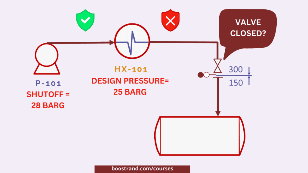
When the procurement cycle of the pump started, the team received the pump’s performance curves. The curves revealed an unexpected shutoff head. Based on the shutoff head, the actual pump shutoff pressure was found to be 28 barg.

A pump shutoff pressure here represents the actual pressure the discharge piping and instrumentation shall face when a valve is closed in the discharge line or due to any other blockage. This means that in this case, the discharge system should withstand 28 barg.
Now, based on the actual pump data, the pump shutoff pressure of 25 barg previously estimated is no longer valid.
So how shall this affect the discharge system?
- For piping and instruments, they already considered a 300 flange rating, which can already withstand the new 28 barg shutoff pressure. Not a big deal!
- Real issue is with HX-101, as the design pressure of the exchanger was only 25 barg. The exchanger was mechanically designed to withstand only 25 barg. Based on mechanical calculations of the exchanger, the maximum allowable working pressure (MAWP) was 26 barg. This means that HX-101 cannot withstand pump shutoff pressure in case a blockage occurred downstream the exchanger while the pump was still running.
Initial Solution: Shutdown Protection
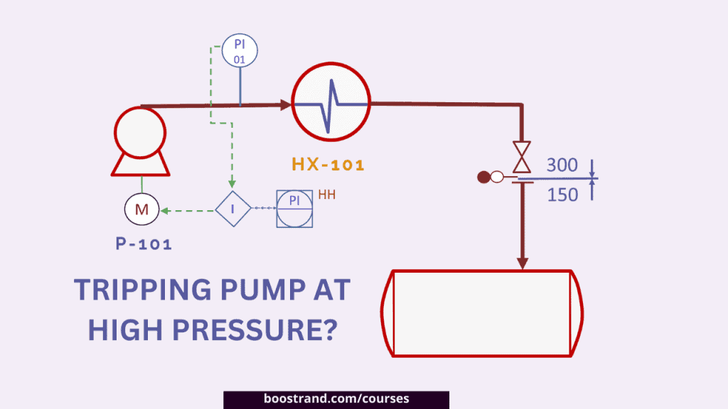
So now we are having a weak point at the pump discharge system. What shall we do?
The first proposed solution was to add a safety interlock system. So when some blockage occurs and the pressure at the discharge reads a very high pressure, this shall trigger a signal from ESD system to stop the pump.
However, this solution faced a significant hurdle. The case is that adding such a protection would need a very reliable shutoff system that has a very low probability of failure on demand. In any SIL assessment, this would need SIL-3 protection. Although SIL-3 can be provided for pressure transmitters using a voting system, the real issue is that the existing Emergency Shutdown (ESD) system was rated at Safety Integrity Level (SIL) 2. This means that the safety function cannot meet the SIL criteria, which means that it is not a reliable protection. If you’d like to know more about how HAZOP and SIL assessment are carried out on a P&ID design, you can check out our P&ID course.
Adding a Pressure Relief Valve?
So what if we added a pressure relief valve as another safeguard in case tripping the pump at a high pressure failed? This would create a layered protection approach acceptable within the SIL framework.
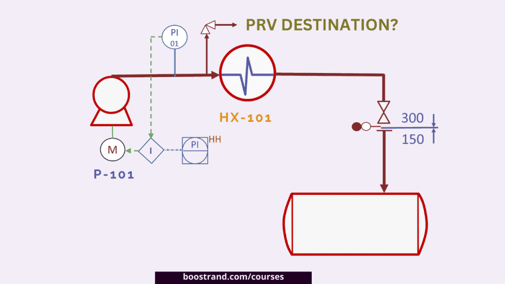
However, this led to a new issue, which is related to the relief destination. Where shall the relieved fluid go?
The high flow rate from the relief valve could not be accommodated by the existing vessel or the flare knockout (KO) drum, as neither was adequate for such capacity. This means that we shall need a new vessel to accommodate this load, which is too costly.
What about the Exchanger Itself?
As it seems that adding more layers of protection would be a very expensive solution, the engineering team started to consult the supplier of the exchanger HX-101.

As fabrication of HX-101 was not yet completed, the team reached out to the supplier to explore options for increasing the MAWP. The supplier offered modifications in the exchanger channel, which was the weakest point in the exchanger.
Chosen Solution
After a cost-benefit analysis of the supplier’s proposed modifications, it was determined that upgrading HX-101 to handle the new shutoff pressure was the most cost-effective route.
The cost was substantially lower than the implementation of overpressure protection involving a new vessel to receive the relief load in addition to pressure transmitters and a pressure relief system.
The heat exchanger supplier implemented the necessary design modifications.
Results
Once the modifications were completed, HX-101’s MAWP was successfully increased to 30 barg. This exceeded the pump’s shutoff head pressure. The discharge system, including the exchanger, piping, and instruments, was fully rated to handle the maximum pressure, ensuring process safety and equipment integrity. This means that the whole system is now inherently safe and can withstand maximum pressure from the pump.
Let's go into P&IDs
P&ID journey: familiarize with P&ID details, anatomy, workflow, discover operation, maintenance & safety best practices
Lessons Learned
- Design Pressure shouldn’t be confirmed before receiving pump curves: Before receiving pump curves, the pump shutoff pressure is considered preliminary. The final say would be by the pump’s supplier. So never use the preliminary value to purchase other equipment.
- Understanding Safety Integrity Levels is highly crucial to ensure whether the system protection is adequate or not.
- Proactive Supplier Engagement: Early and proactive engagement with suppliers can provide alternative solutions that may be more cost-effective than complex system modifications.
Conclusion
The engineering team addressed an overpressure risk through a cost-effective solution that involved upgrading the heat exchanger to handle the pump’s shutoff head pressure. Although this solution caused a cost impact on the project, it was much less than the cost of other solutions. This solution also maintained the project timeline and ensured that the discharge system met all safety requirements without the need for additional overpressure protection measures.
Disclaimer:
This case study is for instructional purposes only and represents a specific instance of addressing a process issue. The solutions provided are not universally applicable and should be considered as a potential approach rather than a definitive remedy. Readers should exercise their own judgment and consult with professionals when applying such strategies to their unique operational contexts.
Start your Career
Access Process Engineering Introduction Course
Share this:
[…] creation of a PFD is typically based on the output of process simulation software. We have discussed plant simulation’s role in a project in the previous article. In a nutshell, process simulation involves using specialized software to model and analyze the […]
