Suppose we have a pump that draws some fluid from a vessel. The pump flow is controlled on the discharge line and there is a minimum flow controller. So we need to determine the pump specifications to perform the required operation.
In order to specify a pump correctly, we need to carry out several calculations. We need to specify its NPSH, we need to determine the pump differential pressure and hence the differential head, and calculate its power. You can check out the pump hydraulics and specifications course explaining these calculations in detail.
Now, after we specified the pump data, we should ensure that the pump is placed in a system that guarantees a smooth pump operation. This would be shown on the pump P&IDs.
So what are the tips we need to consider for the P&ID drawing of a pump?
We need to consider a proper control system to control the pump operation.
We should protect the pump from upset conditions that may cause pump damage.
In addition, the pump should be maintainable, so we need to isolate it in case of a shutdown.
The P&ID should provide the means for the operator to easily monitor the pump performance.
We shall see each of these tips in detail. You can check out the below video, or you can skip the video and continue reading!!
Pump Control
We need to consider a proper control system to control the pump operation. You can check out the article 5 Tips to choose the best process control scheme talking about choosing the proper control scheme in a process plant.
The main control scheme is not developed in the P&ID, but it is determined when developing the Process Flow Diagram or the PFD. P&ID shall reflect this control scheme.
Pump control has many different forms. We may also use a variable speed control to reduce the motor speed, hence changing the pump performance curve.
Or the most common form can be through controlling the pump capacity by placing a control valve on pump discharge to control the system resistance.
Also in order to prevent operating the pump at more than minimum flow, we would need to add a minimum flow control. This can have different forms as well.
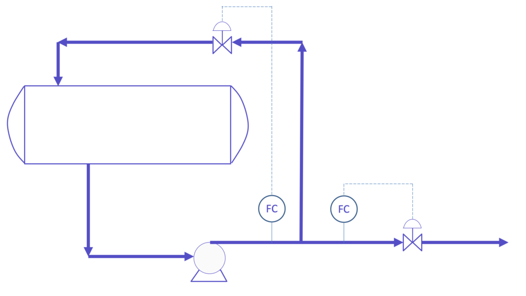
Let’s assume that we shall choose this control scheme:
But the case is that this control scheme is so simplified, we need to show our instrument engineer what is exactly required. So we need to show more details instead of this FC.
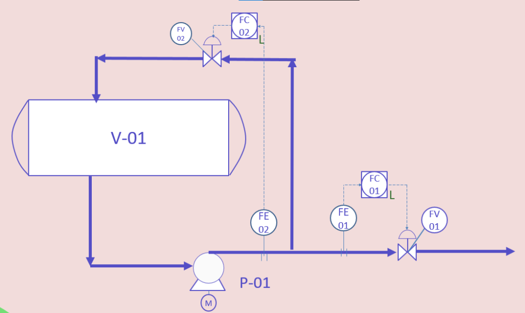
We need to show the flow device, that sends a signal to the controller through a cable, which is FC, the square around the circle in the FC here means that its reading is shown to the operator in the control room, and the control valve will be called FV. We also would add tags, so each instrument or control valve will have a unique tag to be easily tracked. So we have FE-01/02, FC-01/02, and FV-01/02.
What if we want to add an alarm to alert the operator that the flow is low? We can add the L letter on FC-01 and FC-02. This would mean that there should be an alarm so that the operator realizes that there is an issue here with the pump flow. So we will end up with the below scheme.
Protecting the pump from Upset Operating Conditions
We also need to protect the pump from upsets that may cause pump damage.
Pumps for Process Engineers
Learn how the centrifugal and reciprocating pumps operate, how to calculate pump main parameters as a chemical engineer
Low Liquid Level in the upstream vessel
Now, what if the conditions on which we designed the pump were changed to a critical value? For example, this pump draws the fluid from a vessel, we made the NPSH calculation based on the lowest level in the vessel, let’s say it’s 300 millimeters for example.
What if the actual level in the vessel dropped to a value below this level? The pump would cavitate. So in this case, we need to protect the pump if the liquid level dropped to 300 millimeters.
This could be done by stopping the pump once the vessel level reaches the upset liquid level or the low low liquid level.
We also need to warn the operator that the level is dropping and approaching 300 millimeters, so we can give an alarm when the level is at 500 millimeters, which will be a low level alarm. These levels should be considered based on the timing for the operator to respond as explained when we talked about tips on the vessel sizing procedure.
And we need to show the level transmitter on the vessel, as we see it is connected to the vessel through two nozzles covering the low-level range.
The level transmitter will send two signals, a signal to the pump motor to stop the pump in case the level in the vessel reaches 300 mm, and a signal to the control room to show the operator the current readings of the level, this shall also show the low alarm if the level is 500 millimeters, and the low low alarm at 300 millimeters.
Protection from Discharge Line Blockage
Let's go into P&IDs
P&ID journey: familiarize with P&ID details, anatomy, workflow, discover operation, maintenance & safety best practices
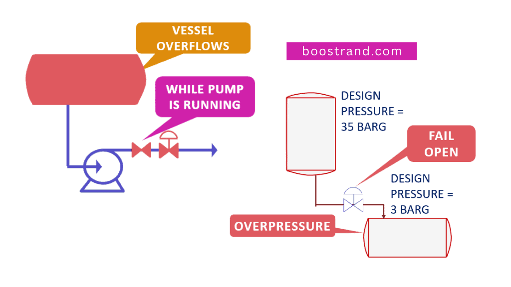
What if, for some reasons, the discharge line is blocked? There may be two issues:
- The first issue is that the pump is susceptible to work at shutoff pressure, which may cause pump damage if it lasted for some time.
- And the second issue is related to an overpressure in the discharge pipe. For a centrifugal pump, this shouldn’t be a great issue as the pipe is supposed to withstand the pump shutoff pressure.
So if the pump shutoff head is 20 barg for example, then the piping should be fully rated, which means that the piping rating should withstand 20 barg.
However, if this pump is a reciprocating pump, this would be an issue, that’s why a pressure relief valve is always installed on pump discharge.
For the above reasons, it’s common to install protection against low pump flow, and sometimes against high pressure in the case of the reciprocating pump. Depending on minimum flow control is not sufficient in many cases, this is because we may need another layer of protection in case the control loop failed. This can be subject to further studies during HAZOP and SIL analyses.
There are other protections related to high motor vibration or current or other considerations, which are recommended by the pump manufacturer.
It’s important to note here that if we are controlling the flow using a flow element, and we shall protect the pump from low flow, we shall need another flow element to send the signal to the emergency shutdown system as these should be two segregated systems.
The pump should be maintainable, so we need to isolate it in case of a shutdown.
The main reason for that is to avoid common cause failure of the same flow element which would paralyze both the control and protection of the pump. This is a general concept that applies to any equipment protection.
Also in order to ensure that there shall be no safety issue if the instrument air was cut and the control valves failed. This can be done by placing the correct valve fail action. This is more explained in detail in our article: What if a Control Valve Failed in a Process Plant?.
So the P&ID showing the pump protection will look like this:
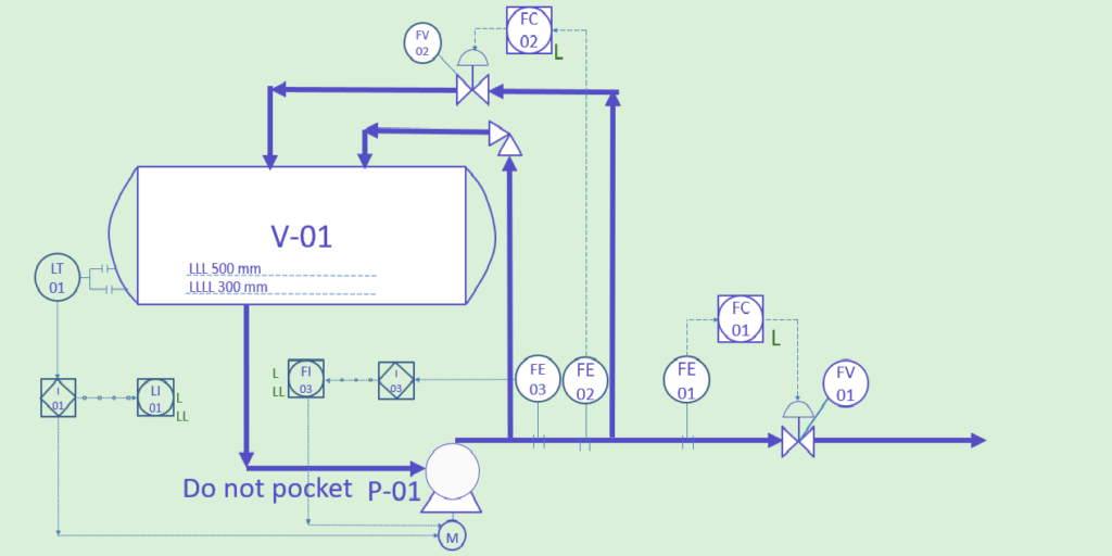
In addition to the above, we should make sure that no vapor shall enter the pump, one of the causes of this scenario is through pockets in the suction line, you may check out our course related to pipe sizing to understand what pockets are. But here in the P&ID, we will just write on the suction line “Do not pocket”.
Isolation, Maintenance and Monitoring
In order for the pump to be maintainable, it should be isolated from the system. Usually, pumps have a spare, so if we need one pump, we install another pump as a spare so that it shall work while the other is out of service, this means that we won’t need to get the system out of service.
That’s why we always need to isolate the pump we are taking out of service from the system. Isolation philosophy varies depending on the company or project standard and depending on system design pressure. There are many isolation considerations not just for pumps, but for different equipment and even for control valves. As this article is related to pumps, we will focus here on some considerations related to pumps.
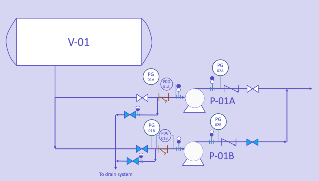
So at each pump, we would need an isolation valve at the suction, and an isolation valve on the discharge.
For the operating pump, the valves will be open, but for the spare pump, the valve shall be closed.
But still, this won’t be enough, a valve may pass fluid to the pump if there is any internal leakage, that’s why we need positive isolation to totally isolate the pump. This would be by installing a spectacle blind on the pump suction and discharge nozzles. By changing the spectacle position to closed, the system would be totally isolated.
So for the operating pump, the spectacle blind shall be open position, and for the spare pump, the blind shall be in the closed position.
Now when we want to operate the running pump, we don’t want the fluid to flow back into the spare pump if the valve on the discharge was left open by mistake or if it is passing fluid, so we shall need to add a check valve at the pump discharge.
Let's go into P&IDs
P&ID journey: familiarize with P&ID details, anatomy, workflow, discover operation, maintenance & safety best practices
We also need to make sure when we isolate the pump to dismantle it that the pipe segment has no trapped liquid, that’s why we shall need drain lines at the lowest point to make sure there is no trapped liquid in the pump system.
So as you see, we need to make sure of considering different operating scenarios and that it shall be a convenient system and safe to operate.
We should also provide the instruments an operator needs to track the operating parameters. These instruments may be instruments to be read in the field only or to be read from the DCS, depending on the criticality of the parameter and the operator’s need.
Here in the case of a pump, we usually add a pressure gauge at the pump suction, and on the pump discharge, which the operator shall depend on during starting the pump by building up the pressure at the discharge system.
This is also applied to the pump strainer at the suction. The job of the strainer is to make sure that no significant solids will enter the pump, especially during start-up when the pipes may not be clean. So if the strainer was plugged, this means more pressure drop.
During start-up, operators need to monitor the pressure drop in the strainer, and when it reaches a certain value, there will be a need to dismantle it and clean it. So we shall need here a pressure differential gauge around the strainer.
These are the basic instruments added to monitor the pump performance. There may be a need for other instruments or to connect these readings to the DCS to be read from the control room depending on the type and service of the pump. The P&ID showing the isolation and maintainability of the pump will look this way:
Conclusion
So as we have seen, there are many guidelines and considerations when developing the P&ID of the pump, whether they are related to control, pump protection and safety, isolation, maintainability, and monitoring the pump performance. This article tried to show some of these guidelines.
There may be other requirements depending on the pump service. Combining all these guidelines in the P&ID drawing is essential in order to make sure we have a safe, operable, and convenient system.
Start your Career
Access Process Engineering Introduction Course
Share this:
[…] creation of a PFD is typically based on the output of process simulation software. We have discussed plant simulation’s role in a project in the previous article. In a nutshell, process simulation involves using specialized software to model and analyze the […]