Shell and tube heat exchangers are the backbone of many industries, offering a versatile solution for heat transfer processes. If you went through any refinery or gas plant or chemical or petrochemical plants, you must have seen plenty of shell and tube exchangers.
In this article, we shall go through the core aspects of optimizing the thermal performance of these exchangers, covering their basic operation, heat transfer equations, design factors, and key parameters that impact their efficiency.
The video below reflects the content of the article, you can watch it or you can continue reading if you prefer reading:
Basic Operation of a Shell and Tube Heat Exchanger
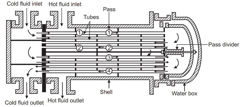
Shell and tube heat exchangers are a type of heat exchanger design where one set of fluids runs through the tube side, while another set flows over these tubes within a shell side. As the fluids flow in their respective pathways, heat is exchanged between them through the tube walls. The fluid flowing inside the tubes either gains or loses heat, depending on its temperature relative to the fluid in the shell. This heat transfer occurs due to the temperature difference between the two fluids.
The below photo shows how the fluid flows in a shell and tube exchanger. You can check out the full video here. If you need to understand more about the basics of a shell and tube heat exchanger, you can check out this video:
Main Exchanger Performance Parameters
As the case with any exchanger, the basic equation from where all exchanger parameters can be evaluated is the heat transfer equation:

So what are the parameters of this equation, and how do they affect the exchanger performance? Let’s analyse each parameter
Duty: Determining Heat Transfer Requirement
Duty is the essential factor driving heat exchanger design. It represents the amount of heat that needs to be transferred between fluids. The basic equation describing heat duty is the famous equation:

Through this equation, we can see that the heat lost by the cold side is equal to the heat gained by the cold side. This shall equal the heat transferred through the exchanger, which is equal to U.A.MTD as described above. So here the exchanger is required to provide the area and performance parameters that can achieve the required duty.
As we see, the duty depends on the following:
- Flow rates of hot and cold sides: As we are expecting more flow rates from the hot side or from the cold side, then this means that we shall need higher duty.
- Specific Heat Capacity: A fluid with higher heat capacity would need more heat to increase its temperature, which also means more exchanger duty.
- Temperature difference between inlet and outlet: So if the hot fluid is expected to be cooled down from 200 C to 30 C, this would require much more duty than the case if we cool it down from 200 C to 150 C.
So as we see, heat duty is highly important when we analyse the heat exchanger’s performance. But is it the only factor? Actually, no, we still have other factors. So let’s see them.
Exchanger Thermal Design
Explore shell and tube exchanger thermal design aspects and basis for optimizing heat exchangers with various HTRI examples.
Heat Transfer Coefficient: Efficiency Indicator
Heat Transfer Coefficient is a key factor when studying the performance of heat exchangers. A higher heat transfer coefficient means more efficient heat transfer between hot and cold sides. If we can maximize the heat transfer coefficient, this means that we can minimize the exchanger’s heat transfer area, which means lower exchanger dimensions, i.e., lower exchanger fixed cost.
So to understand the heat transfer coefficient in deep, let’s see the following:
As we can see in the photo, heat is transferred from the shell side to the tube side. In other exchangers, it can be from the tube side to the shell side, depending on the position of the hot and cold fluid in the exchanger. So what shall happen during heat transfer?
There are 5 resistance types here that shall act against heat transfer:
- Resistance in shell bulk fluid: For example, a fluid with high viscosity, low thermal conductivity and flowing with a low velocity shall have a very high resistance against heat transfer.
- Fouling Resistance in Shell Side: A fluid with high fouling factor shall cause precipitation of solids on tube outside surface, which shall impede heat transfer.
- Tube Metal Resistance: As the heat transfer is made on tube outside surface, this means that thermal conductivity of tube material shall be a factor affecting the heat transfer, although it may not be the most effective factor.
- Fouling Resistance in Tube Side: Same as 2 but for fluid flowing in the tube. The fouling layer shall precipitate on the tube surface inside.
- Fouling Resistance in Tube Side: Same as 1, but for tube fluid.
So here, if we want to calculate the heat transfer coefficient, this can be done through the below equation:
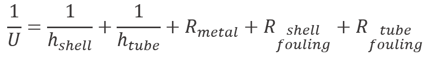
So, the above equation is the formulation of the resistances against heat transfer. Here, our target is to maximize (U) to reduce (A), as we highlighted above. This depends on these factors.
Shell and tube film coefficients
As we stated above, film coefficients highly depend on fluid velocity on the shell side and the tube side. As the velocity increases in shell, heat transfer resistance in the shell shall drastically decrease.
On the other hand, the heat transfer resistance shall highly increase in case of dealing with a fluid with high viscosity.
Heat transfer coefficient is also affected by other factors such as density, thermal conductivity, heat capacity, ..etc. Shell and tube exchangers are distinguished by their high heat transfer coefficient compared to air coolers, which always yield in much smaller exchanger dimensions. This is commonly studied versus the water consumption when choosing between air coolers and water coolers.
Fouling Resistance
Fouling resistance negatively affects the heat transfer coefficient. As we stated above, we have a fouling layer on the shell side and the tube side.
Fouling resistance highly depends on the fluid type. Some fluids are clean, so we can consider them to have too low fouling resistance. On the other hand, we need to consider high resistances for fouling fluids.
There is some guidance on the value of fouling factors in TEMA standard. It states the expected fouling resistance against each fluid type. The below table states some of these factors:
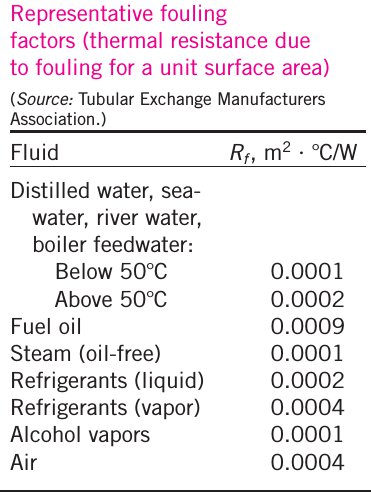
It’s worthy here to note that fouling factor is crucial when determining the TEMA type of the exchanger as exchangers with high fouling service need to be more frequently cleaned than exchangers with clean service.
Resistance in Tube Metal
The tube metal has its share in the overall resistance against heat transfer. This depends on 2 factors:
- Tube Thickness: A higher thickness means a higher resistance
- Tube Thermal Conductivity: This depends on the tube’s material of construction.
Understanding Thermal Resistance helps Optimize Sizing
So when carrying out the thermal design of a shell and tube exchanger, it’s highly important to understand where the controlling resistance lies. The below reflects the HTRI output of 2 exchangers showing how the thermal resistance is distributed along the exchanger.
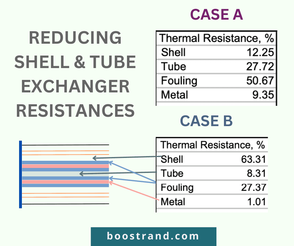
So here in case A, the resistance in tube side (27% of total resistance) is much more than that of the shell side of shell side(only 12%), this would mean that enhancing velocity on the tube side would lead to much better heat transfer than enhancing it in shell side because there is already no much resistance. If the fouling layer hasn’t yet been formed or the exchanger is frequently cleaned, the heat transfer coefficient would significantly be much higher as the fouling resistance in both sides constitutes 50% of the total resistance.
However, when we look at case B, we’ll find that the resistance in the shell side constitutes 63% of the total resistance, so here the design engineer should focus on increasing the heat transfer coefficient in the shell side, most probably by adding more baffles. This shall be the most significant solution as it shall deal with reducing the controlling resistance.
Mean Temperature Difference: Driving Force between Both Sides
The Mean Temperature Difference (MTD) serves as the driving force for heat transfer between the two fluids. In a heat exchanger, heat flows from the fluid at a higher temperature to the fluid at a lower temperature. The greater the MTD, the more substantial the driving force between hot and cold sides. This means more efficient heat transfer process.
The MTD is calculated by getting the logarithmic mean temperature between the hot side and cold side at both the inlet and outlet of the exchanger. This can be shown in the figure below.

As cooling water is always provided at a temperature less than air, using water coolers will always be a privilege against air coolers when cooling a fluid to a temperature that is too close to air temperature.
Heat Transfer Area: Exchanger Size & Cost
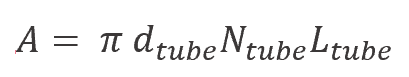
Heat Transfer area reflects the dimensions of the exchanger and the number of tubes. A higher heat transfer area would mean an exchanger achieving a higher duty at the same heat transfer coefficient and MTD. The below equation calculates the heat transfer area:
The heat transfer area depends on the below factors:
- Tube Outside Diameter: The heat transfer occurs on the tube surface. That’s why tube diameter is a key factor in calculating heat transfer area.
- Number of Tubes: The total number of tubes in the heat exchanger affects the heat transfer area. More tubes generally provide a larger area for heat transfer but can also lead to increased complexity and cost.
- Tube Length: The length of the tubes is another critical factor. Longer tubes provide more surface area for heat transfer but can also result in higher pressure drop and increased cost.
- Shell Diameter: The diameter of the shell itself plays a role. A larger shell diameter allows for more number of tubes and, consequently, a larger heat transfer area. However, limitations may be based on the selected TEMA (Tubular Exchanger Manufacturers Association) type. In addition, the diameter of the shell is the most critical factor affecting the cost of the exchanger.
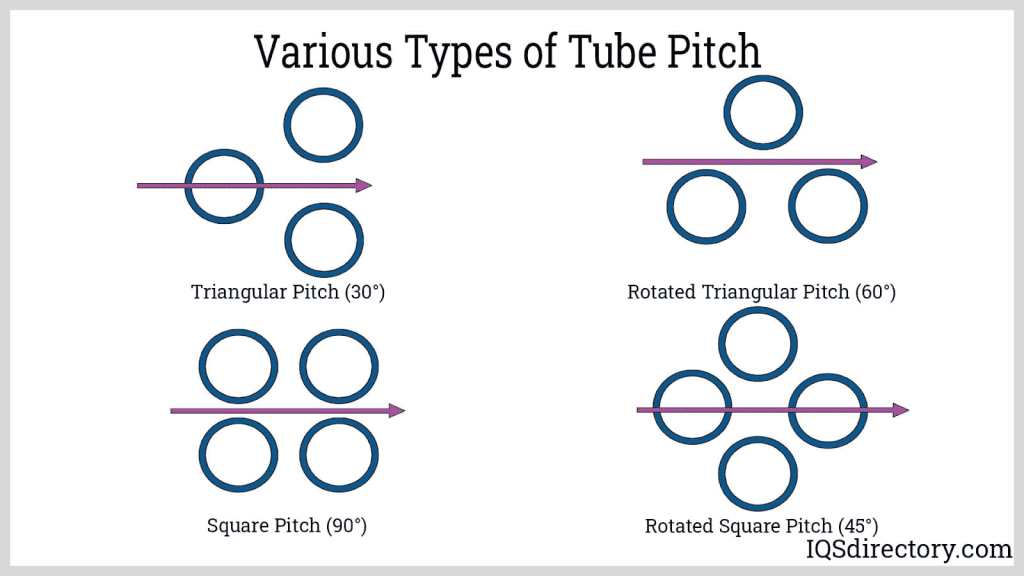
- Tube Pitch and Pattern: The arrangement of the tubes within the shell, including tube pitch (the distance between tube centers) and tube pattern (how the tubes are arranged), is also a critical factor that influences the heat transfer area. This is because, through different arrangements within a specified shell diameter, we get a different number of tubes, which means a different heat transfer area.
These factors are highly critical, affecting the heat transfer area, coefficient, pressure drop, exchanger maintainability,…etc. That’s why we shall talk about them in more detail later.
Evaluating Exchanger Performance Parameters
So, as we see, there are many factors affecting the performance of the exchanger. Let’s go through them.
Is Exchanger Area Sufficient to Achieve the Duty?
Determining if an exchanger’s area is sufficient to handle the required duty is a critical assessment. This is commonly done through dedicated software such as HTRI and Aspen EDR. The common procedure followed is as follows:
- Based on exchanger dimensions and geometry, the exchanger’s heat transfer area is calculated from the equation A= π NDL.
- Based on process conditions such as hot and cold flow rates, inlet and outlet temperatures, and physical properties, the Heat Transfer Coefficient (U), and the Mean Temperature Difference(MTD).
- Based on the duty (Q), the Heat Transfer Coefficient (U), and the Mean Temperature Difference (LMTD), we can get the required area from the equation Q= UAΔTm
- If the area calculated from step 1 is greater than that calculated from step 3, then this exchanger can achieve the required duty. Otherwise, we would need to change the exchanger’s design to achieve the duty.
Based on step 4, we can get the ratio between the calculated area and the required area. This should be greater than 1 for the exchanger to achieve the duty.
In HTRI, this is commonly called as %Overdesign. This is equal to:
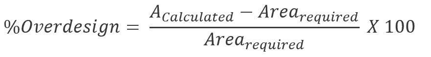
So for the exchanger to achieve the required duty, the %Overdesign should be greater than 0.
Pressure Drop: Balancing Energy
Exchanger Thermal Design
Explore shell and tube exchanger thermal design aspects and basis for optimizing heat exchangers with various HTRI examples.
Pressure drop is a crucial parameter that can affect the sizing of a shell and tube exchanger. So, we may have cases where the exchanger’s current area can already achieve the duty. However, it exerts a very high pressure drop either on the shell side or on the tube side. In this case, we may need to change the design of the exchanger if this pressure drop affects the hydraulics of the system.
Usually, we can get the required pressure drop for each side by analyzing our process and the hydraulics of our system (try Calcpad for hydraulic calculations for piping, pumps and control valves). Based on this analysis, we may find that the allowable pressure drop in the shell is 1 bar. On the other hand, we are just limited by a maximum pressure drop of 0.5 bar in the tube side. This means that we may change the pipe size, pump differential pressure, or control valve pressure drop based on the pressure drop in the exchanger.
This means that when we carry out the thermal design of the exchanger, we should ensure from the software result that the actual pressure drop shouldn’t exceed 1 bar on the shell side and 0.5 bar on the tube side. Otherwise, we may end up with less flow entering the exchanger on the affected side.

Factors Affecting the Performance of an Exchanger
So as we have seen, sizing a shell and tube exchanger is a complicated procedure. There are lots of inputs and factors that can affect its performance, whether we are talking about process conditions, fluid physical properties, or exchanger geometry. Each of these has lots of details that should be considered in order to reach the optimum exchanger sizing.
Now, let’s discuss the crucial factors that affect the thermal design of a shell and tube exchanger.
Fluid Velocity
The velocity of the fluid is one of the crucial components that can highly affect the heat transfer coefficient. This is applied on both the shell side and the tube side.
That’s why a thermal design engineer should always try to tweak the geometry of the exchanger to maximize the heat transfer coefficient on both sides. This is commonly done by maximizing tube passes on the tube side, and maximizing baffles on shell side.
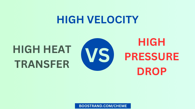
Maximizing fluid velocity ensures maximum heat transfer efficiency at minimum exchanger dimensions. However, a higher velocity also means a higher pressure drop. That’s why we should always ensure the balance between a high heat transfer coefficient while ensuring that the pressure drop is within its allowable limits.
Fouling Factor
As we highlighted above, the fouling factor is highly crucial when analyzing the heat transfer coefficient of the exchanger. During thermal design, we are expected to consider a valuable figure of fouling resistance for shell and tube fluids. This ensures that the exchanger can work at the maximum fouling conditions.
In addition, a high fouling fluid means the exchanger should be cleaned. This means we should consider the TEMA type that can help the operator clean the exchanger. You can check out the details about choosing the exchanger TEMA type in this article.
Fluid Allocation: Which fluid is in the Shell Side, and which is in the Tube Side?
So we have a shell and tube heat exchanger where heat is exchanged between 2 fluids. Which fluid shall be on the shell side, and which fluid to be on the tube side?
This depends on several factors:
- Which fluid is more fouling? The velocity on the tube side is typically higher than on the shell side. In addition, cleaning the tubes is much easier. So it’s better to allocate the fluid in the tube if it is more fouling.
- Which fluid is more corrosive? A corrosive fluid will need a material of construction that is resistant to corrosion, which is often more expensive. As the shell side needs much more metal weight than the tube side, it will be less costly to allocate the corrosive fluid to the tube side.
- Is there a great difference in pressure between both sides? Also, if the fluid is operating at high pressure, this means that the exchanger should withstand this pressure and even higher depending on the upset scenarios. Same as in the case of corrosion, this will be more costly if we allocate a fluid with higher design pressure in the shell side. That’s why it will be better to consider the higher pressure on the tube side and apply the 10-13 rule on the shell side. If you’d like to understand more about how to determine design pressure and design temperature of equipment and how this affects the safety of the plant, you can check out our P&ID common practices course.https://courses.boostrand.com/courses/piping-instrumentation-diagram-preparation-guidelines
- Which allocation shall give better heat transfer? In some cases, we may discover that the fluid flowing in the shell side has a very low heat transfer coefficient compared to that of the tube side. If this happens, this would lead to a low overall heat transfer coefficient based on the equation explained above. If we switched the allocation of both fluids, and As the velocity in the shell is typically much less than the velocity in tubes, this may lead to much better exchanger performance. This is because it shall reduce the gap between both fluids and increase the overall heat transfer coefficient, which shall lead to less area, or in other words, less exchanger dimensions.
As we can see, there are various factors affecting fluid allocation. These factors may even contradict each other. So we have to evaluate these factors well and determine which factor to consider and which factor to sacrifice.
Process Engineering Masterclass
Become a Professional Process Engineer, discover process engineering career, role, activities and common practices with access to most of the courses here.
Exchanger TEMA Type
The exchanger TEMA type is a highly important factor that affects the geometry of the exchanger. So, for example, an exchanger with a floating head will result in much fewer tubes in a shell than the case of a fixed tubesheet exchanger. In addition, to ensure easy exchanger cleaning, there shall be limitations on the exchanger’s geometry parameters for floating head exchangers.
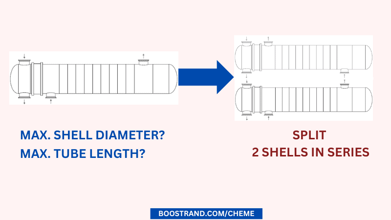
For example, some standards consider a maximum shell diameter of 60 inches and a tube length of 24 feet to ensure easy bundle removal. This means that there shall be a greater limitation on the maximum duty that an exchanger can achieve. If we are considering this limitation while we have a great duty to achieve, then we shall need to add more than one exchanger shell.
MTD
We have gone through the importance of Mean Temperature Difference in thermal design. Here it’s important to highlight that MTD is highly critical when it is less than 10 C. This is because if the conditions changed so that MTD is reduced, this will drastically affect the required area to achieve the duty. Remember that we get the required area from the equation (Q=U.A.MTD).
So, if the conditions show that the MTD is reduced from 10 C to 8 C, we shall require a 20% greater exchanger area. If the MTD is reduced from 5 C to 3 C, we shall require 20% greater exchanger area. If it was reduced from 2 C to 1 C, we shall need 100% greater exchanger area. That’s why it’s a common practice to consider a valuable temperature approach in order to avail a reasonable exchanger area.
Exchanger Geometry
The geometry of the exchanger is affected by many parameters. So let’s check them out.
Shell Diameter
The shell diameter is an essential parameter in the design of a shell and tube heat exchanger, as it directly affects the heat transfer area, pressure drop, and velocity of the shell-side fluid.
As we increase the shell diameter, this means that more tubes are available within a shell, which means a greater exchanger area. In addition, this means a lower pressure drop in both shell side, and tube side.
Selecting the appropriate shell diameter is crucial for optimizing the thermal performance of the exchanger and minimizing the cost and complexity of the design.
Tube Length
A greater tube length means a greater exchanger area, but it also means a higher pressure drop in both shell side and tube side.
Tube Passes
Increasing tube passes is a common method that is used to increase the heat transfer coefficient. This is because more tube passes means that the flow in tube side passes through less number of tubes per pass, which means more velocity and less resistance in tube side.
But as we increase the heat transfer efficiency and reduce resistance in tube side, we are also increasing the pressure drop in the tube side. So here we should always consider the proper optimization against the 2 factors.
Baffle Spacing & Cut
Baffles are flat plates or structures that are strategically placed within the shell of the heat exchanger. They create a controlled flow pattern for the shell-side fluid, ensuring that it doesn’t simply flow straight through the shell but instead encounters the tubes in a way that maximizes heat exchange. In addition, they act as mechanical supports to the tube bundle.
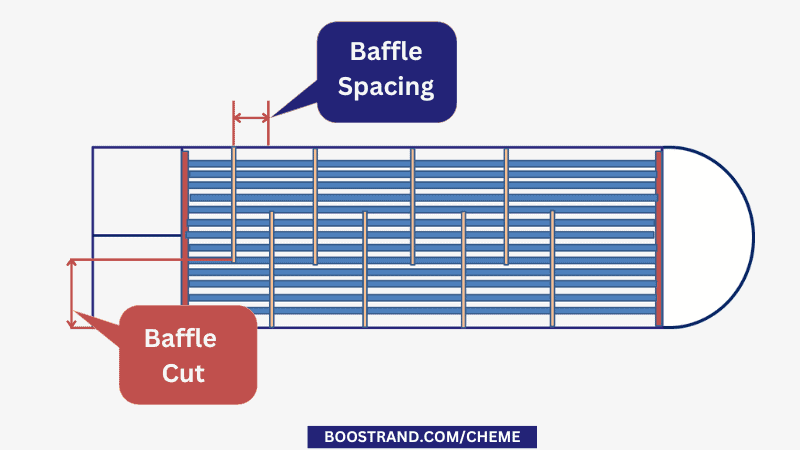
This is because as we increase the number of baffles, or in other words decrease the baffle spacing. This shall cause greater turbulence in the shell side, which means less heat transfer resistance.
However, on the other hand, this shall also lead to a greater pressure drop in the shell side.
Tube Outside Diameter
The tube diameter is commonly considered either 0.75 inch or 1 inch. A larger tube diameter would mean less number of tubes per shell and a lower pressure drop in the tube side. However, a smaller tube diameter is more susceptible to plugging. That’s why a 0.75-inch tube is not recommended for fouling fluids.
Tube Pattern
Tube patterns (pitch) impact fluid flow and heat transfer. A triangular layout (30 or 60) can enhance heat transfer but also increase pressure drop, while a square or rotated square layout (45 or 90) can balance these two aspects.
Tube Thickness
The choice of tube thickness is mainly based on TEMA requirements. This depends on both tube diameter and tube material. So for a tube with a diameter of 0.75-1 inch, the tube thickness ranges from BWG 12 to BWG 14.
The tube thickness has a minor impact on exchanger sizing. This is related to slight changes in velocity that can affect the heat transfer coefficient and to tube metal resistance against heat transfer. Tube thickness also affects pressure drop on the tube side.
The greatest effect of tube thickness is related to the exchanger’s weight, which is a main factor affecting the cost of the exchanger.
Exchanger Arrangement: Series or Parallel?
In many cases, we may find that one shell is not enough to achieve the required function of the heat exchanger. In this case, we shall need to add more than one shell in series, in parallel, or a combination of both.
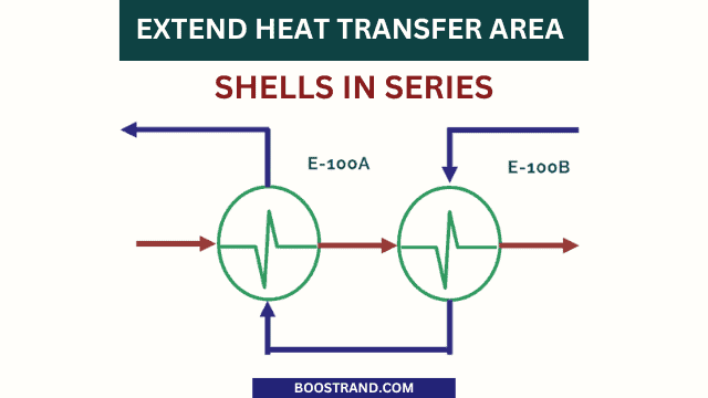
Shells in Series
So what if we have limitations of the shell diameter or in the tube length? This means that we are having limitations on the heat transfer area per shell. So we shall add another shell in series to extend the heat transfer area.
Also we can use more than one shell in series to avoid issues related to temperature cross. Temperature cross in heat exchangers occurs when the temperature of the cold fluid exceeds the temperature of the hot fluid at some point in the exchanger profile. This can be shown in the below photo.
Temperature cross will cause heat to be transferred in the opposite direction at some point. This would lead to sharp reduction in the heat transfer efficiency.
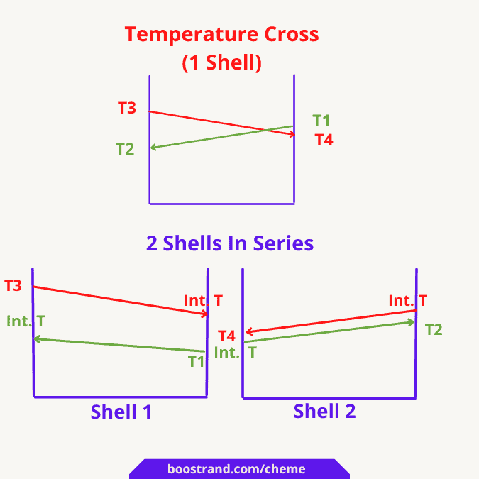
In this case, adding another exchanger in the series can be a solution. This can split the exchanger’s profile between the 2 shells in order to avoid the temperature cross. The below photo illustrates an example.
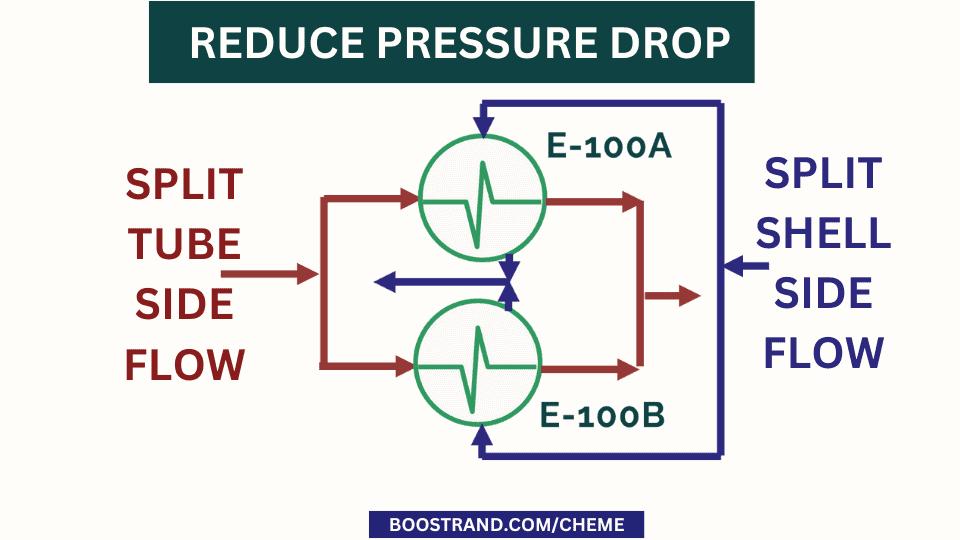
Shells in Parallel
In other cases, we may find that the exchanger is experiencing a high pressure drop, whether in the shell side or in the tube side. We have reached the shell diameter limitation, which also means the maximum number of tubes per shell, so we cannot provide more cross-sectional area for the shell or the tube side.
So, in this case, we can use 2 shells in parallel. This is to split the flow to each shell. This shall finally yield a much lower pressure drop.
Adding 2 shells in parallel shall also lead to a greater heat transfer area. However, it shall also impact the heat transfer coefficient as we are dealing with less velocities. This shall still achieve a higher duty than one single shell. However, its effect from duty point of view is much less than using 2 shells in series.
So at the end, a thermal design engineer should understand the pros and cons of each arrangement in order to reach the optimal thermal design. It’s highly important here to ensure the correct configuration in P&ID design as it can highly affect the piping arrangements.
Conclusion
Shell and tube heat exchangers are versatile and efficient solutions for a wide range of heat transfer applications. Understanding the nuances of their thermal design can help engineers optimize their performance and cost-effectiveness. From tube length and diameter to shell diameter, baffle spacing, tube passes, and pressure drop considerations, every aspect plays a significant role in the heat exchanger’s efficiency. By mastering these elements, engineers can design robust and efficient shell and tube heat exchangers that meet their specific application requirements.
Start your Career
Access Process Engineering Introduction Course
Share this:
[…] creation of a PFD is typically based on the output of process simulation software. We have discussed plant simulation’s role in a project in the previous article. In a nutshell, process simulation involves using specialized software to model and analyze the […]