As we discussed in a previous article, Pressure Safety Valves (PSVs) play a crucial role in maintaining safe operations in chemical process engineering by protecting equipment from overpressure conditions.
Due to their high importance and criticality, we should have a clear understanding of the parameters that highly affect the PSV operation and minimize their issues when opening for different relief scenarios. In the article highlighted above, we talked about some of these parameters such as PSV types and flare backpressure.
However, there are other important parameters. In this article, we shall highlight some other parameters (still not all) that should be considered to ensure a smooth relieving operation.
If you’d like to continue watching the video, you can just click on the below. Otherwise, you can continue reading!
PSV Operating Mechanism
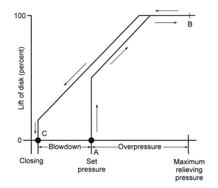
API-520 shows the above curve reflecting the opening mechanism of a PSV by plotting the valve lift versus the pressure exerted on it. This is done in the below steps:
- As system pressure reaches the PSV set pressure, the valve begins to open (point A)
- As there is still not enough valve lift at the set pressure, the pressure continues to rise to the accumulation pressure (overpressure), and the valve will fully open to relieve the excess pressure (point B).
- Once the pressure is relieved, the valve moves to the blowdown phase where it reseats, preventing further release of fluid (point C). Note here that the valve lift didn’t restore to 0% until the blowdown pressure is reached, not at the set pressure.
This means that the valve lift percentage is highly affected by the current pressure at the PSV, which means that the proper sizing of the PSV should consider the proper valve lift against the relief stages. Otherwise, this may lead to several issues. These issues can be:
- Slow response against overpressure, not relieving enough fluid. This can lead to an accumulation pressure higher than required, which means that the vessel is subject to overpressure.
- Rapid response, by opening and closing rapidly. This can lead to damage to the valve seat and disc.
- Premature opening (simmer), this means that a portion of the process fluid is relieved to flare, which is an undesirable condition.
- PSV cannot open enough, excessive backpressure opposes the lifting force that is holding the valve open, which can alter the valve’s response to overpressure and potentially reduce its flow capacity
Each of these issues can compromise the safety and efficiency of a process system (check out our P&ID course to understand more the role of PSV as a layer of protection). That’s why it’s essential to follow established sizing and selection criteria, such as those outlined in API standards, to ensure that PRVs function as intended, providing reliable protection against overpressure scenarios.
So here in this article, we shall focus on some of these parameters that shall affect the PSV operation.
FACTOR 1: Accumulation Pressure (Overpressure)
Accumulation pressure, also known as overpressure, is the maximum pressure that may build up above the set pressure of the valve during discharge before the valve reaches full lift (from point A to point B). It is imperative for the PSV to achieve full lift within the accumulation limit to ensure efficient pressure relief without damaging the valve or the system.
Exceeding this limit can lead to the valve not opening sufficiently, consequently failing to relieve enough pressure which may cause system failure.
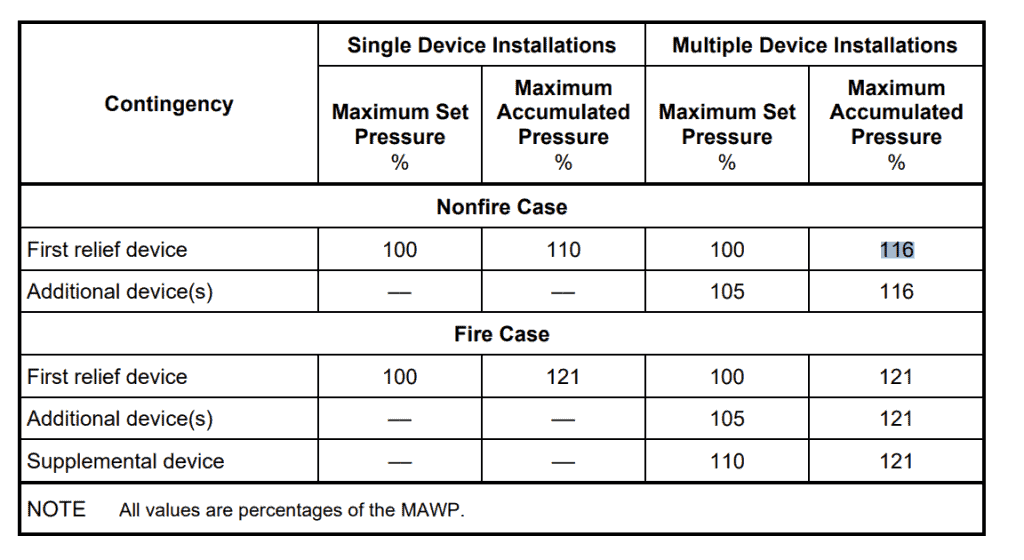
API 520 shows the overpressure limits for single and multiple installations of a PSV (in case multiple PSVs shall operate in parallel not spare PSVs). For the fire case, ASME section VIII designates the pressure accumulation limit to be 121% of the vessel’s MAWP. For other overpressure cases, the accumulation limit is 110% for single valves and 116% for multiple valves. For ASME Section I coded boilers, the accumulation is even more stringent as only 6% overpressure is accepted.
FACTOR 2: Blowdown
Blowdown is the difference between the set pressure at which the PSV starts to open and the pressure at which the valve reseats (from point A to point C).
ASME Section VIII considers blowdown to be 7% of set pressure (i.e. PSV totally closes at 93% of set pressure), while ASME Section I considers 4% (96% of set pressure). Blowdown should be reduced for a pilot-operated valve as it operates at a pressure too close to set pressure. That’s why it is considered to be 3% to avoid interference with operating pressure.
It is essential to correctly size the PSV to have an appropriate blowdown. Too high blowdown can cause slow PSV response and PSV opening at much less pressure than set pressure, which can cause lots of disturbance.
PSV and Relief System Sizing
Learn PSV sizing for different scenarios, understand depressurization, blowdown & flare system components, and analysis.
On the other hand, too low blowdown shall lead the PSV to rapidly cycle between relieving and non-relieving states, leading to damage in PSV seat and disc.
Proper PSV sizing is necessary to achieve an appropriate blowdown. Excessive blowdown can result in a slow PSV response and the PSV opening at a much lower pressure than the set pressure, causing disturbances. Conversely, insufficient blowdown can lead the PSV to rapidly cycle between relieving and non-relieving states, potentially damaging the PSV seat and disc.
FACTOR 3: Effect of Inlet and Outlet Piping
Inlet and outlet piping configurations significantly impact PSV performance. A high pressure drop in the inlet piping would lead the PSV to sense a lower pressure than the actual pressure. This shall cause PSV chattering and interference with the PSV blowdown characteristics.
To prevent this, it’s critical to ensure that the pressure drop in the inlet line does not exceed 3% of the PSV’s set pressure. In our line sizing course, we have given various examples about how to calculate the pipe size for different services.
Conversely, the sizing criteria for outlet lines include backpressure and velocity considerations; if not properly designed. A very high velocity can lead to choked flow, while a very high pressure drop shall cause high backpressure on the PSV. Both can affect the PSV’s ability to relieve pressure effectively and potentially lead to unstable valve operation.
Therefore, the outlet piping should have a maximum velocity ranging from 0.3 to 0.7 Mach, and a comprehensive backpressure analysis of the entire flare network must be conducted to ensure that the outlet piping is appropriately sized.
FACTOR 4: Multiple Relief Scenarios
Various relief scenarios can lead to different relief loads on a PSV. If not managed properly, this can result in chattering—a condition where the PSV rapidly opens and closes.
Suppose we have a PSV that should handle two scenarios; one for inlet valve failure, and the other for fire. When calculating the orifice area in case one of these scenarios happened, they yielded highly different orifice areas.
For instance, an inlet valve failure might require an orifice size designated as ‘H’ (0.785 in^2), while an external fire scenario might necessitate a much larger ‘P’ designation (6.3 in^2).
This disparity presents a dilemma. If we just chose to go for sizing the PSV for the larger scenario and choose the larger orifice area, this would mean that in the event of an inlet valve failure, the PSV is oversized. An oversized PSV means that an excessive flow shall pass through the PSV. This is because when a PSV opens, the full orifice area shall be utilized. This excessive flow rate can cause PSV chattering, which can lead to damage on the long run.
Solution: Staggered PSV Set Pressures
One recommended solution is to install multiple PSVs with staggered set points. By employing two PSVs of different sizes, the smaller one opens first at a lower pressure, gradually relieving the system. This shall mainly be utilized in the non controlling scenario. If still overpressure occurs while the small PSV cannot handle it, the larger PSV shall open at this point.
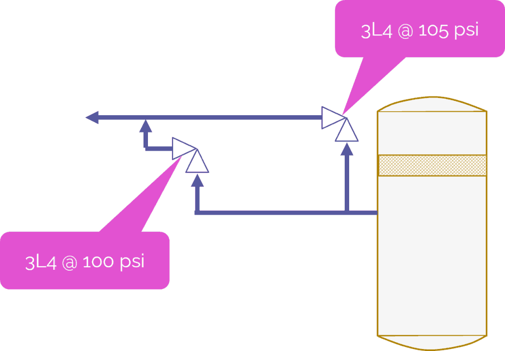
So if, for example, if the set pressure is 100 psig, we shall consider a smaller PSV opening at 100 psig in case of inlet valve failure. If pressure continues to rise, the larger PSV opens at 105 psig, handling the higher flow requirements without causing the PSV to relieve excessive load and cause PSV chattering. table).
Or we can have another solution, which is to choose 2 identical PSVs with identical size. This size shall be larger than H and lower than P. It shall be chosen so that the sum of both areas shall handle the largest scenario. So, for example, we may choose an orifice “L” with an orifice area of 2.8 in2, so that 2 PSVs will lead to a total area of 5.6. If the required area is less than 5.6, then we can choose 2 X 3L4 PSVs.
If we need a larger area, we can choose 2 X 3M4 PSVs. In this case, one valve shall be set at 100 psig, and the other at 105 psig.
Conclusion
In conclusion, the proper sizing and configuration of PSVs are paramount to the safety and efficiency of chemical process engineering systems. Understanding and managing the factors that affect PSV performance—such as accumulation pressure, blowdown, piping effects, and multiple relief scenarios—help prevent operational issues like chattering and ensure that overpressure conditions are effectively mitigated. Always refer to appropriate standards, such as API 520, and seek vendor input as needed when designing and installing PSVs.
Start your Career
Access Process Engineering Introduction Course
Share this:
[…] creation of a PFD is typically based on the output of process simulation software. We have discussed plant simulation’s role in a project in the previous article. In a nutshell, process simulation involves using specialized software to model and analyze the […]