As process engineers, we design equipment, piping, and other plant components to operate within the conditions that achieve the best operational efficiency and yield on-spec products. However, no one can guarantee that the plant shall always operate within the specified operating envelope. This is because any plant is still subject to lots of disturbances. Disruptions such as improper feed, equipment malfunctions, control failures, human errors, or external events (e.g., power failure, and fires) can lead to extreme deviations in process variables. These deviations—such as excessively high or low pressures, temperatures, liquid levels, or flow rates— pose severe risks to personnel, equipment, and the environment.
For example, excessive flow to a separator can lead to high liquid levels, and consequently, overflow, which can lead to hydrocarbon spillage or carryover into downstream systems not designed to handle liquids. A malfunction in the cooling water pump can cut the cooling water to coolers, resulting in a high exit temperature from water coolers or runaway reactions in reactors. If some valve was closed by mistake on the discharge in a reciprocating pump, this shall lead to high pressure on the discharge side. This can cause damage to discharge piping and equipment as the pump is pushing liquid in a blocked path.
Such scenarios can result in catastrophic equipment failure, fires, explosions, injuries, or fatalities. As process engineers, our responsibility is to consider the proper safeguards in the P&ID. These safeguards would prevent these deviations or mitigate their consequences before they escalate.
Layers of Protection
To address these risks, process engineers employ a layered approach to safety, where multiple barriers work independently to prevent, control, or mitigate hazards.
Inherently Safe Design
In the beginning, we should try as much as we can to consider an inherently safe design. This is achieved by ensuring that all equipment and piping are designed to withstand the maximum pressure and temperature the system may face. For example, the design pressure of the centrifugal pump discharge shall be based on the pump shutoff head in addition to maximum suction pressure. This would eliminate the risk of overpressure in case some blockage occurred in the discharge system. In a previous article, we talked about a safety issue due to the change in the pump shutoff head leaving the discharge system vulnerable to overpressure, so we had to re-increase the design pressure before the exchanger is fabricated.
However, considering an inherently safe design may not always work. We have scenarios that can yield too high pressure, and designing the system to withstand this pressure won’t be feasible. For example, we can consider the discharge system to withstand the pump maximum discharge pressure if the pump was of centrifugal type. We can determine the maximum discharge pressure (based on shutoff head) using our Calcpad pump sizing calculator.
But for reciprocating pumps, they don’t have a shutoff head. That’s why a pressure safety valve (PSV) should always be installed to open in case a blockage occurred on the pump discharge.
Also there are other scenarios that may even affect the integrity of equipment to withstand overpressure such as fire. Fire can reduce the material strength significantly if the unwetted surface is subject to very high temperatures, and if the vessel is pressurized, it can fail at a pressure less than its design pressure in case of fire.
So here we may need to find other methods. IEC-61511 classifies the layers of protection to apply risk reduction as per the below photo:
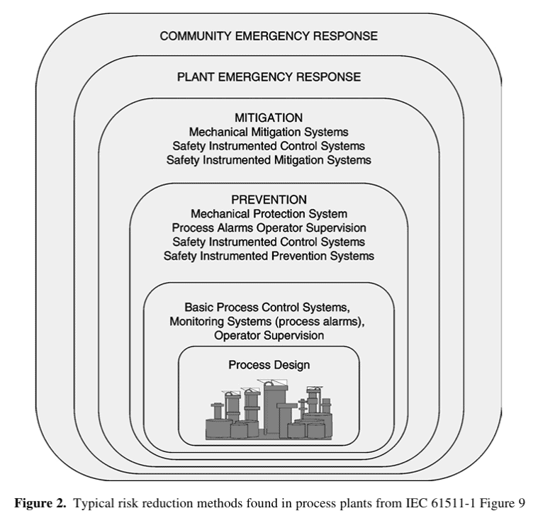
Process Design, Monitoring and Control
The first layer focuses on eliminating hazards through design choices. This can be done through proper process design, where system arrangement and equipment sizing are considered to make more room for operational instabilities.
For example, the vessel may be large enough to handle the excess flow, which would reduce the risk of high levels, we have talked in separators sizing article about calculating liquid levels in vessels based on time for operator to respond. Another example is a water cooler designed for maximum expected water temperature with an excess exchanger area to handle instabilities in the cooling water system so that the outlet temperature of the process fluid is within limits.
This also applies to placing proper control systems that give a proper response to instabilities or placing instruments in place so that plant operators can easily monitor important process parameters. Although most of these may not always be considered a reliable safeguard, they would, for sure, reduce the frequency of upset conditions.
Start your Career
Access Process Engineering Introduction Course
Preventive Safeguard: Alarms and Operator Intervention
Alarms alert operators to deviations (e.g., high-pressure or high-level alarms). Operators can then manually intervene, such as shutting down a pump or adjusting valve positions. This helps eliminate the risk. In addition, operational procedures help operators monitor plant conditions properly and reduce operator mistakes, which shall also help in system protection.
Adjusting level alarm set points in vessels is a main factor in vessel sizing. Calcpad vessel sizing module lets you see directly how level alarm settings affect required vessel size..
Preventive Safeguard: Safety and Shutdown Interlocks
So what if there is an issue with the control system, a specific parameter keeps on rising, and operators didn’t respond? This would lead to a severe consequence. For example high liquid level can lead to overfilling, high pressure can lead to mechanical failure in the piping or equipment, liquid release and loss of containment, and may be explosion.
So if a safety issue or a severe consequence is expected, we shouldn’t just rely on process control or operator response. We would need even another system to stop the source of hazard such as inlet fluid or pump to prevent consequences from escalation. This is done through shutdown actions or interlocks. We shall talk about them in detail in this article.
Mitigative Safeguard: Mechanical Devices or (PSVs)
Now, we have a risk of overpressure in the system, and we have added some shutdown action to stop the source of hazard. However, we know that the consequences of overpressure would be devastating, and there is always a probability that this shutdown system fails on demand. It could also happen that the shutdown system may not be able to stop the source, such as fire scenario for example.
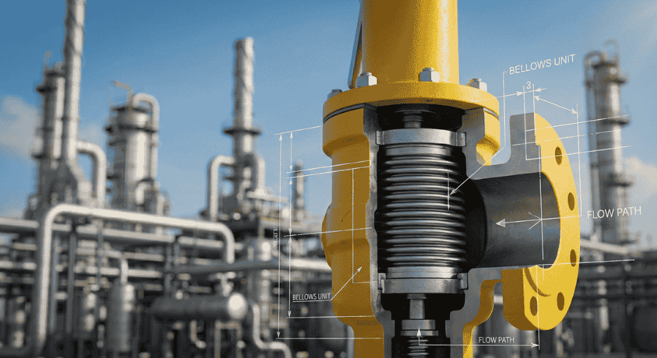
So we shall need another type of protection through mechanical device to mitigate overpressure. This is commonly a pressure safety valve or PSV. PSVs act as the final layer to mitigate consequences if all else fails. They relieve excess pressure to protect equipment from rupture. We have talked about pressure safety valves in various articles, you can check them out in this link.
Other protection Methods
As we see in the hierarchy provided by IEC 61511, it talks about other protection layers. However, the above is what concerns us as process engineers responsible for plant design. We should always ensure that the protection layers we place are enough and that the plant operators won’t use emergency plans or that the community would need to interfere.
We should always ensure that multiple safeguards exist to address hazards at different stages, reducing reliance on any single layer.
In this article, we shall talk about one of the most important safeguards a process engineer should consider in plant protection, which is the shutdown protection of the plant, or in other words, safety interlocks.
So let’s start.
Start your Career
Access Process Engineering Introduction Course
Safety / Shutdown Interlocks: Examples and Applications
Safety interlocks are automated systems designed to detect abnormal conditions. Based on this detected condition, the shutdown system shall take immediate action to prevent a severe consequence before it happens. The below shows some examples of shutdown interlocks:
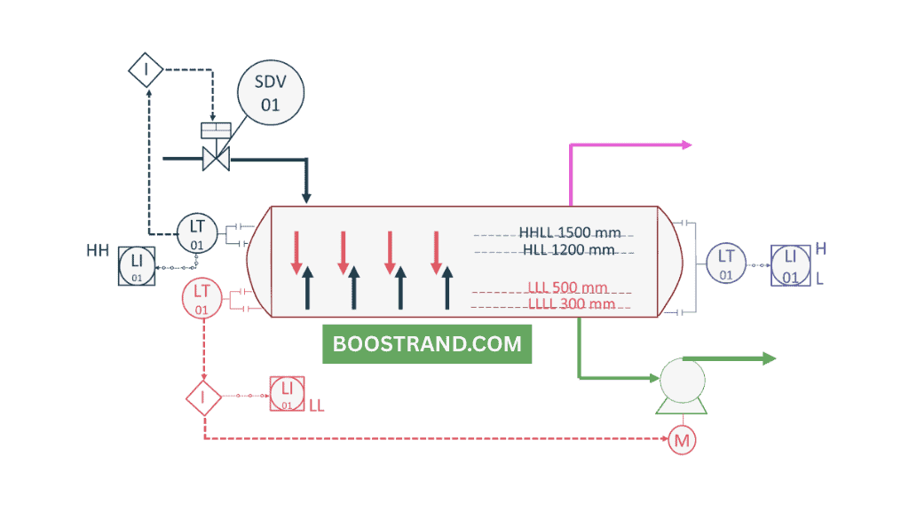
Example 1: High Liquid Level Shutdown
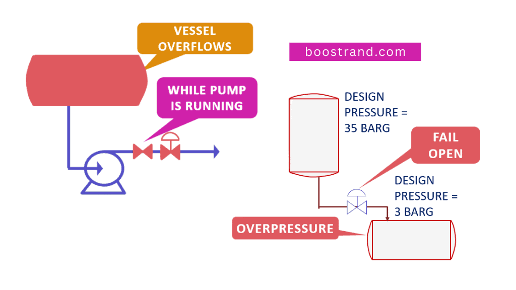
- Scenario: A separator vessel risks overfilling due to a faulty level controller.
- Consequence: Vessel overflows and liquid starts to go from gas outlet. leading to huge disturbance in downstream system.
- Interlock: A high high level signal triggers the closure of the inlet valve, stopping further liquid inflow.
Example 2: Reciprocating Pump Overpressure Protection
- Scenario: A pump discharge pressure rises dangerously due to a downstream blockage.
- Consequence: Overpressure leading to rupture in discharge piping or equipment.
- Interlock: A pressure transmitter sends a signal to trip the pump motor, preventing mechanical damage.
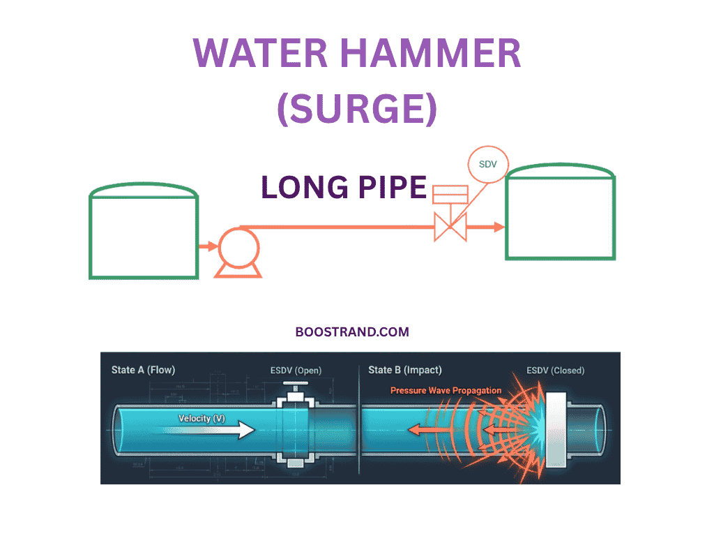
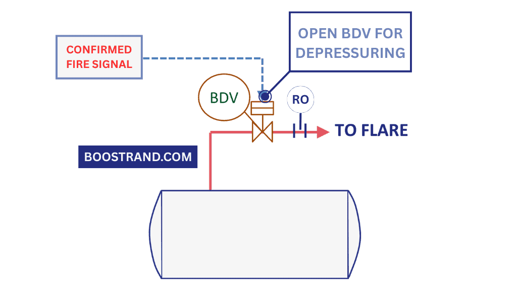
Example 3: Fire-Induced Depressurization
- Scenario: A fire near a pressure vessel raises temperatures.
- Consequence: Vessel failure as it cannot withstand this high temperature while operating at high pressure.
- Interlock: A confirmed fire signal (from heat detectors or gas sensors) initiates automatic vessel depressurization. This shall open the blowdown valve to send the gas to flare to reduce internal pressure and prevent rupture.
Example 4: High Temperature in the reactor
- Scenario: Temperature is getting too high in the reactor.
- Consequence: Runaway reaction leading to overpressure in the reactor, probable explosion and gas release.
- Interlock: High high temperature alarm sends a signal to open the valve for cold water quench line to stop the reaction and prevent overpressure.
So, we see that shutdown interlocks are used to prevent an abnormal situation from escalating and protect the equipment by preventing or mitigating the risk.
Anatomy of a Safety Interlock
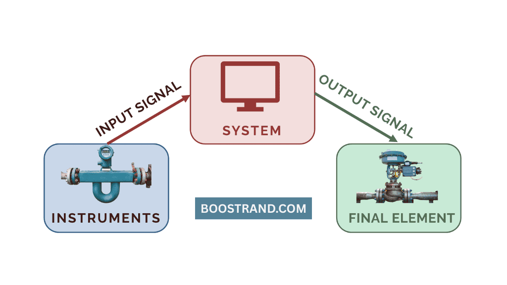
A safety interlock operates as a Safety Instrumented Function (SIF), comprising three components:
- Sensors/Initiators
- Measures the parameter or variable, sends a signal of the reading to the control system or shutdown system, e.g. pressure or level or temperature transmitters.
- Example: A pressure transmitter continuously monitors reactor pressure and sends the reading to the operator in the control room.
- Input signal from the instrument to the instrument to the logic solver through hard-wired cables.
- Logic Solver (SIS/ESD)
- Receives signals from sensors, evaluates if a safety action is needed, and triggers outputs.
- Systems include Safety Instrumented Systems (SIS) or Emergency Shutdown (ESD) systems.
- Example: ESD / SIS receives input signal from pressure transmitter and compares it reactor to high high pressure setpoint. If the pressure reaches the high high set point, it gives high high alarm and ESD shall send an output signal to final element to take action.
- Output signal from the logic solver to the final element through hard-wired cables.
- Final Elements
- Execute the protective action (e.g., valves, pumps, motors).
- Example: Based on the output signal sent from the ESD, the inlet feed valve closes to isolate a high-pressure section from the source and protect the reactor from overpressure.
So when we deal with Safety Instrumented Functions (SIF), we must have a deep understanding of its components. This is because each of these items is a separate component that has its conditions to work, and the whole loop should be very reliable and working in harmony as we are dealing with plant protection from major safety issues.
If any of these loop components have an issue, the whole SIF shall be disturbed and won’t act as a protection. For example, if there is an issue with the transmitter giving false reading, it won’t trigger the logic solver to take the action, or if the logic solver has some bug, it won’t send the output signal to the valve to open or to close.
So here we should take care of the reliability of whole SIF as this is a plant protection against major safety issues which can cause fatalities or injuries or equipment damage.
HAZOP: Identifying Gaps in Safeguards
A Hazard and Operability (HAZOP) study plays a pivotal role in any project to identify the hazards a plant may face and analyze the safeguards considered in the design.
This is done through the following steps:
- Identifying risks resulting from deviations in process parameters (e.g., “high pressure,” “no flow”)
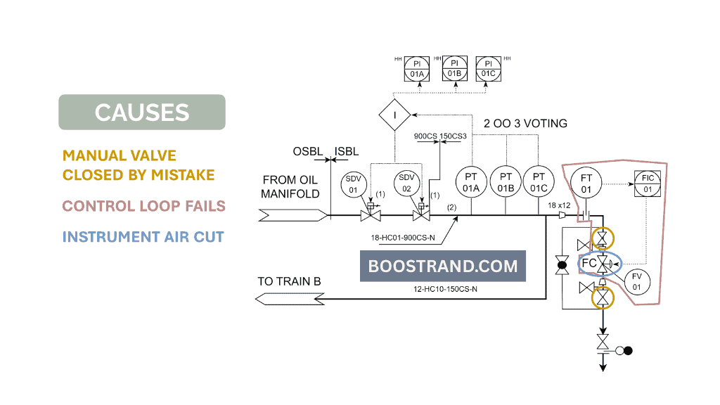
- Analyzing the causes that can lead to this deviation, such as manual valves getting closed by mistake or control loop failure.
- Checking the consequences resulting from these deviations and how this shall affect the system such as overpressure leading to failure.
- Listing the available safeguards to face these deviations, e.g. pressure safety valves or shutdown interlocks.
- Adding recommendations if the safeguards were not found to be sufficient.
Example: A HAZOP on a distillation column identifies that a high-temperature deviation could lead to column overpressure. Nothing prevents high temperature except the control of the cooling medium to the condenser or the heating medium to the reboiler. This is not considered a safeguard as the control loop itself can be a source of deviation in case it fails.
That’s why the HAZOP team recommended installing a SIF to trip the reboiler heater by adding a shutdown valve to stop the flow of the heating medium to the reboiler, which is the source of heat in our case, in case the temperature reached the high high set point.
SIL Assessment: Quantifying Interlock Reliability
Now as HAZOP identifies different safeguards, it’s time to analyze their reliability. Here comes the role of the Safety Integrity Level (SIL) assessment. Through SIL sessions, the project team studies the criticality of each SIF or shutdown loop and how the risk looks in case the SIF fails when needed. Based on this analysis, we can determine the reliability of the loop, which is represented in its SIL rating.
Steps in SIL Assessment
- Risk Matrix: Rank consequences resulting from the deviation based on its severity (e.g., fatalities, environmental damage) and likelihood.
- Layer of Protection Analysis (LOPA): Quantify risk reduction provided by existing safeguards (e.g., BPCS, PSVs).
- SIL Target: Assign a SIL rating (1–4) based on residual risk. Higher SILs demand a lower Probability of Failure on Demand (PFD).
Example: A high-pressure SIF in an ethylene cracker requires SIL 2, meaning its PFD must be between 0.01 and 0.001 (i.e., 99–99.9% reliable). To achieve this, redundant pressure transmitters (2oo3 voting) and dual-block valves are used.
In our P&ID course, we have talked about HAZOP and SIL studies giving more extensive examples of how they work and how a process engineer should consider different protection layers in his design.
Process Engineering Masterclass
Become a Professional Process Engineer, discover process engineering career, role, activities and common practices with access to most of the courses here.
Cause & Effect (C&E): Blueprint for Interlock Implementation
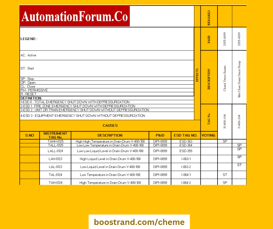
The Cause and Effect Matrix documents the logic of each interlock, specifying:
- Initiating instruments (e.g., pressure switch PS-101).
- Logic requirements (e.g., 2oo3 voting for sensors).
- Final elements (e.g., close valve XV-201).
- Time delays (e.g., 10-second delay before valve closure).
Now, based on the cause and effect, SIS vendors are expected to implement the shutdown actions and apply the shutdown logic to the plant. The process engineer, along with the instrumentation engineer, are responsible to ensure that the vendor implemented the shutdown logic in the ESD system correctly as specified in the cause and effect. This is done through Factory Acceptance Tests (FATs) and Site Acceptance Tests (SATs).
Conclusion
Safety interlocks and shutdown systems represent a critical layer of protection in process plant design and operation. As process engineers, we must carefully consider and implement these systems to prevent potentially catastrophic events. The systematic approach of identifying hazards through HAZOP studies, determining required safety integrity levels (SIL), and implementing robust cause-and-effect logic ensures that our plants operate safely and reliably.
Start your Career
Access Process Engineering Introduction Course
Share this:
[…] creation of a PFD is typically based on the output of process simulation software. We have discussed plant simulation’s role in a project in the previous article. In a nutshell, process simulation involves using specialized software to model and analyze the […]