Separation is an essential process that is carried out in any plant, whether it was an oil facility, a gas plant, a refinery or a petrochemical complex, or in any other chemical processing plant. There are many separation methods depending on the fluid physical properties, whether it was the difference in boiling points as in the case of distillation towers, solubility in a specific solvent as in the case of absorbers or extractors, or in other aspects where we have another separation techniques.
In this article, we shall talk about gravity separators, where fluids are separated when there is a great difference in their densities. You can watch the content of this article in the below video, or you can skip the video and continue reading:
Basic operation of Separation Vessels
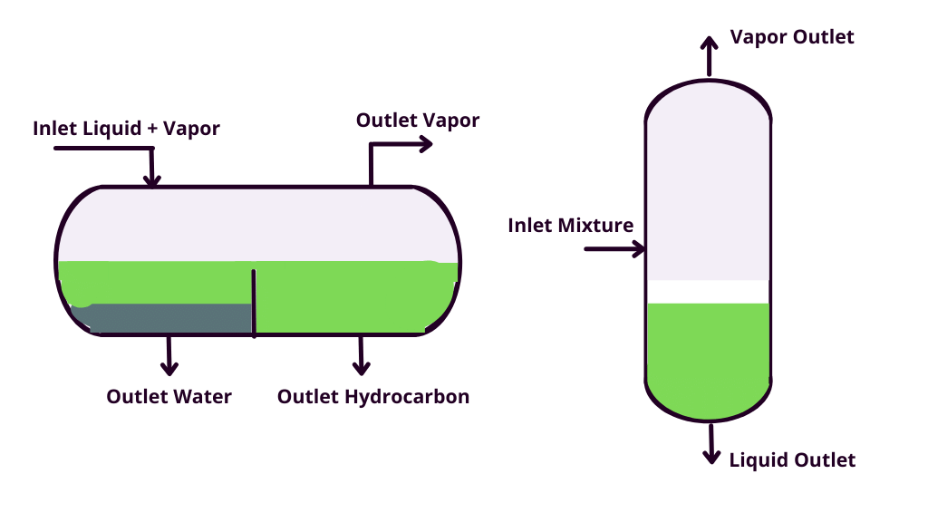
So for a two-phase gas-liquid separator, we have a gas that is much lighter than a liquid, so simply the gas goes up and the liquid goes down. For liquid liquid separators, we have a liquid that has less density than the other, for example, oil is lighter than water, so the liquid with more density will be settled to the bottom and we will have two liquid layers.
We may even have three phase separation in one vessel, the most famous application is in oil facilities, where the crude oil from the wells is accompanied with associated gas and formation water. So, when it is introduced to a three phase separator, gas exits from the top of the separator, and water is separated from formation water in the bottom.
Separation Requirements
In order to choose the separator type and specify its required size, we need first to define what we need from the separator. This includes for example:
The Degree of Separation
How much liquid entrainment is accepted in the gas? If the exit gas from the vessel is entering a compressor for example, then liquid entrainment may cause damage to the compressor. In this case, there shall be stringent separation requirements related to liquid entrainment. However, if this gas is going to another vessel or to an absorber or a distillation tower for further separation, then in this case, the liquid entrainment requirements can be relaxed. A process engineer should understand what he needs from the separator as this shall affect the sizing of the vessel and shall issue a vessel datasheet to be purchased based on this sizing.
The same can be applied in the case of liquid liquid separation. If we are talking about oil and water separatio as an example example, the traces of water may affect the downstream process. This may be the case if we are talking about poisoning a reactor catalyst for example. On the other hand, the traces of oil in water can be an environmental issue related to the disposal of this water, and based on the amount of oil, we shall need more complex systems so that this wastewater can reach the allowable disposal limits specified by the environmental law.
All these factors can drastically affect the sizing and internals of the vessel. They are generally expressed in the maximum liquid particle size. So they should be well defined from the beginning.
Separator Design and Vessel Sizing
Master separator design criteria, internal selection & sizing calculations for vertical & horizontal vessels with examples.
Densities of liquid and gas
The settling velocity is a critical factor that determines the required vessel size. The main factor affecting the settling velocity is related to the density of the liquid and the vapor. We shall see this more in detail when checking out Brown Souders equation and the gas handling capacity factor (K factor).
So when we have a great density difference between the phases to be separated, this would mean that separation will be easier. This is because the light fluid shall go upwards faster, and the lower liquid shall be settled faster. In this case, we shall need a vessel with a less diameter, which means less cost.
Liquid and Vapor Flow Rate
Liquid and vapor flow rates affect the type of separators, whether they are vertical or horizontal. So when the vapor flow rate is dominant, we usually go to the option of a vertical separator. However, if the liquid flow rate is dominant, in this case, it would be better to be a horizontal vessel.
In addition, a high flow rate means greater vessel dimensions. This is to ensure that the residence time of the fluid in the vessel is enough and that there is enough space for separation to occur.
Are there Emulsions?
Emulsions are formed when one of the two immiscible liquids is existing in the other liquid in the form of tiny droplets that cannot be separated normally by gravity except when too much time is passed. If emulsions are existing and we need to separate them, then in this case a vessel won’t be a practical solution as it should be extremely large.
That’s why we some internals to coalesce the emulsion droplets to be of a greater size that could then be separated by gravity. Coalescers are very common to be used in this case.
So it’s very important to understand the nature of the fluid in order to choose the appropriate internals.
Special Devices
Sometimes, depending on the service, special devices may be added. For example in case of emulsions, coalescers may be needed. In other cases, we may need a heating coil. These internals should be well integrated with the vessel size and will have minimum liquid level requirements as the heating coil should always be covered with liquid. If foams are expected to appear, proper internals should also be considered.
Horizontal vs Vertical Separators
Separators can be either vertical or horizontal. Usually this is specified in the beginning of the project when issuing the PFD. But it would be verified when carrying out the vessel sizing.
In general vertical vessels are used more frequently when the flow rate of gas is large compared to that of the liquid. With the help of an inlet device, the liquid is directed to the vessel’s bottom, and the gas moves to the top. As the gas is moving to the top, it gets rid of liquid entrainment. The entrainment could be further reduced by mist eliminators. In these cases, not much liquid is expected to be collected in the bottom, so the liquid level is not expected to cause the vessel to have a too large tan to tan or height. This also gives an easier control of liquid level as the response in the vertical vessel’s level shall be fast.
Also, a vertical vessel has the advantage of a smaller plot area, which can help in a congested plant.
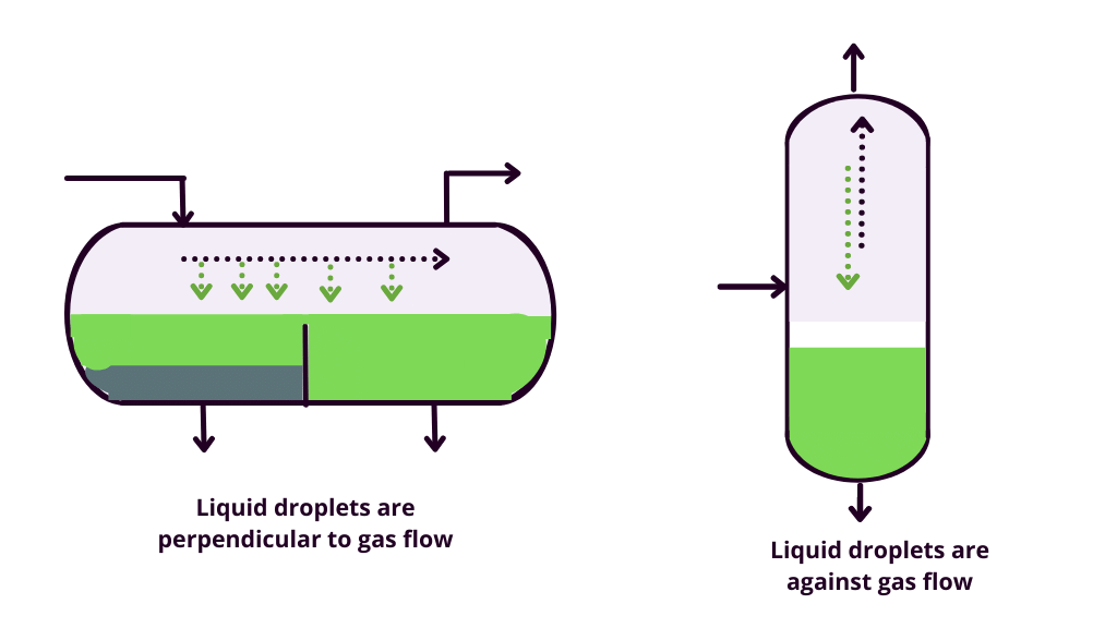
On the other hand, if we have a dominant liquid flow rate compared to the gas flow rate, then in this case a horizontal vessel will be preferred as the liquid can occupy its required volume without having an exaggerated vessel’s tan to tan or length. In addition, the liquid droplets in the gas will be moving perpendicular to the gas flow rather than moving to an opposite direction in the gas as in the case of a vertical vessel, which enhances the separation.
Vessel Internals
Vessel internals are devices that are used at the vessel inlet or outlet or within the body of the vessel to enhance the separation. These internals can help a lot reduce the vessel size, which shall mean reducing the final cost of the vessel.

Inlet Devices
Inlet devices are typically used on the vessel inlet nozzle to enhance the separation. This is done through reducing the momentum of the entering fluid and hence causing the liquid droplets to be dropped to the bottom of the vessel.
There are several types of vessel inlet devices as:
- Deflectors
- Half-open pipe
- There are other proprietary devices as Shell Schoepentoeter™ which are usually the most effective devices.
Separator Design and Vessel Sizing
Master separator design criteria, internal selection & sizing calculations for vertical & horizontal vessels with examples.
Outlet Devices
Outlet devices are usually installed on the vapor outlet to get rid of liquid entrainment as much as possible. This can be done through several devices as:
- Wire mesh demisters
- Vane packs
For the liquid outlet nozzle, API 12J states that a vortex breaker may be located over to prevent gas or oil entrainment with the bottom liquid.
Three Phase Separator: Weir Vs Boot?
In order to achieve both gas liquid and liquid liquid separation in one vessel, we would need a vapor space, a compartment for the heavy liquid, and a compartment for the light liquid.
The compartment can be a weir or a boot. From separation and level control point of view, the weir is much more efficient. However, it won’t be feasible when the heavy liquid flow rate is too low compared to the light liquid especially if there is no stringent separation requirement with respect to maximum droplet size. In this case, considering a small boot for the collection of a heavy liquid can be considered.

Vessel Sizing Parameters
We need to determine some criteria and the basis on which we shall proceed in the vessel sizing procedure. So let’s examine them:
Gas Handling Capacity (K Factor)
Separation of liquid droplets from the gas depends mainly on gas velocity in the vessel. For an efficient separation to take place, the gas velocity should be lower than the critical or terminal gas velocity. The gas velocity is determined through Brown Souders equation:
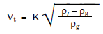
As we see, the critical gas velocity depends on the liquid and gas densities. In addition, we can see that it also depends on the gas handling capacity factor or what is famously known as K factor. The K factor depends on the type of the vessel and the outlet device used. There are some guidelines regarding its values in API 12J and GPSA. However, it should be advised by the vessel manufacturer.
Separator Design and Vessel Sizing
Master separator design criteria, internal selection & sizing calculations for vertical & horizontal vessels with examples.
Separation degree
As we stated above, the separation degree is important to be defined before starting to size the vessel. In general, API 12J states that liquid carryover is normally less than 0 .1 gallon per MMSCF.
For liquid liquid separation, it is usually expressed in form of particle size. For example we may define that the maximum droplet size of water in oil is 150 micron and the maximum droplet size of oil in water is 400 micron. The criteria of course depends on the project and the standards that shall be used.
Residence Times
Residence time is an essential factor to that should be considered in vessel sizing to allow adequate phase separation. As fluid has more time to settle in the vessel, we can obtain better separation.
However, retention time is not just related to separation. Vessels, in addition to being used for separation, are also used as a surge drums in many cases. So if there is some process instability upstream of the vessel, the vessel can still provide the liquid to the downstream process for some time without the need to shut down the system until the liquid level is too low. The plant operator can utilize that time to solve this issue and the need for a shutdown will be eliminated in this case. If you’d like to know more about the common means to provide easy plant operation when preparing a P&ID, you can check out our P&ID course.
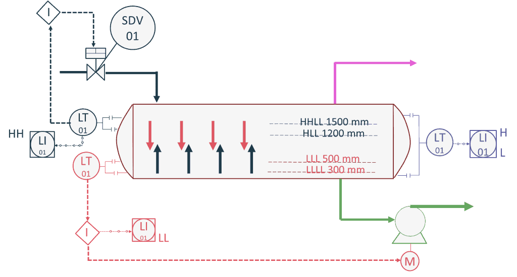
However, the more retention time is considered, the more vessel dimensions will be. So the retention time shouldn’t be exaggerated anyway. The retention times are used to size obtain these levels:
- Low low level, where the outlet flow from the vessel would be stopped. This is usually linked with safety interlocks to stop the pump or close the shutdown valve in case of outlet control valve failure. You can check out the examples I gave in Discover Tips for Preparation of a Pump P&ID and What if a Control Valve Failed in a Process Plant? for more details on this point.
- Low level, where the operator would receive an alarm. The usual timing between low level and low low level is 1 minute or depending on the instrument range, whichever is greater.
- The High liquid level, where the operator would receive an alarm. The usual timing between low level and high level is from 3 to 15 minutes, depending on the criticality of the service.
- The high high level, where the inlet flow to the vessel shall be stopped, the usual timing between high level and high high level is 1 minute or depending on the instrument range, whichever is greater.
Just to note, these values are arbitrary values. The exact values depend on the project or company standard.
Conclusion
So as we see, there are many factors that determine the choice of the vessel, its internals, and sizing procedures. It’s important to make sure all the requirements and criteria are well considered before sizing the vessel as this shall affect the final result of the sizing process.
Start your Career
Access Process Engineering Introduction Course
Share this:
[…] creation of a PFD is typically based on the output of process simulation software. We have discussed plant simulation’s role in a project in the previous article. In a nutshell, process simulation involves using specialized software to model and analyze the […]