Process control is essential in any plant to ensure that the operating parameters are within their acceptable limits. When we open a process flow diagram (PFD), we can see different control loops controlling various equipment in any plant. In all these various industries, process control schemes are considered, whether we are talking about oil and gas, petrochemicals, water treatment, pharmaceutical, chemical, or food industry. In this article, we shall go through the considerations that are usually taken to ensure we have chosen the correct control scheme. So let’s start!
If you like to watch the video on YouTube, you can click below. Otherwise, you can continue reading:
Tip 1: Determine the parameter to be controlled
Most Critical Parameter
In order to choose the optimum control scheme that can do the job, we need first to determine the parameter that needs to be controlled. So if we want to control the operation of the separator, the parameters most probably will be the separator pressure and the liquid level.
- If this is a pump or a compressor, then it shall be a flow controller.
- If it was an exchanger or an air cooler, then the controlled parameter would be the outlet temperature of the target stream.
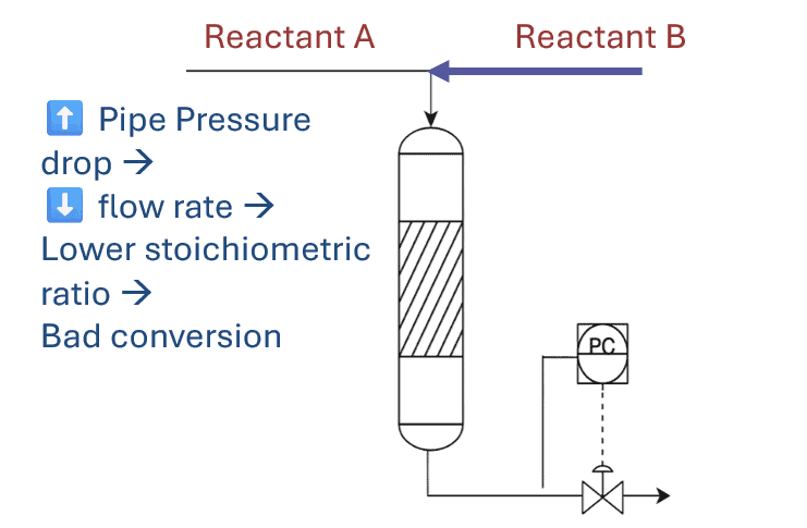
- For a reactor, we shall need to control the flow ratio of the reactants to adjust the reaction stoichiometric ratio. It may be also a pressure or a temperature controller, depending on the type of the reaction.
- For a tower, we need to control its pressure and the inlet flow. We can also be controlling the temperature of specific trays as these are among the most important factors affecting the tower operation.
So it’s important here to define the parameter that will mostly affect the performance of the system we want to control in order to choose the control scheme that fits our purpose.
Easiest Parameter to be controlled
When we want to control the performance of the system, we should try to choose the parameter that shall be easier to control and directly affects the system. For example when we want to control the performance of a pump, it’s common use a flow controller not a pressure controller, although the pump is mainly used to rise the pressure of a fluid.
This is because the pump performance curve plots the volumetric flow rate against the pump head. This means that the pump output is head not pressure. So if there is a variation in fluid density, adding a pressure set point may not guarantee that the pump is at a desired flow region.
For example, if we have a fluid with a density ranging from 700 to 800 kg/m3, and the pump is expected to work at 100 m3/hr. If we opened the pump curve, the expected head at 100 m3/hr is 200 m for example. So if the fluid density is 700 kg/m3, the discharge pressure needed to give 100 m3/hr shall be around 14 barg. However, if the fluid has a density of 800 kg/m3, the pressure shall be around 16 barg.
This means that the set point of the controller should be continuously changed depending on the current fluid density, which is not very practical. This article explains in detail how the fluid density affects the pump operation.
So here the point is that controlling the pump operation through flow would be much easier than controlling the discharge pressure.
Still that doesn’t negate the fact that pressure control is used when we need to keep a constant pressure at the system where the pump is sending fluid to and it is more important to maintain than the flow. Here of course we should ensure that pump is operating in the desirable flow region. This would most probably need a minimum flow recycle line as shown in the above photo.
Start your Career
Access Process Engineering Introduction Course
Tip 2: Choose the optimum control method for the equipment
Now after we have chosen the parameter that shall control our system’s operation, we need to choose the best control method that fits our system. This can be from the point of view of operational stability, equipment safety or cost optimization.
Example: Exchanger direct cooling vs bypass cooling
Suppose we have a fluid that is cooled by water in a water cooler. We need to ensure that the outlet temperature of the fluid has a certain value, so we shall place the temperature controller based on the reading of the outlet fluid. We can change the temperature by changing the flow of the cooling water, so we can just add a control valve on the cooling water line.
.png)
However, if the fluid is cooled by another process fluid, changing its flow rate may negatively affect the process (you can check out what coolant to use in the article Heat Exchanger Vs Air Cooled Exchanger: Which one to use? ).
In this case, we can control the fluid outlet temperature by through a bypass controller, where a portion of the fluid inlet bypasses the exchanger and mixes with outlet fluid which is overcooled to reach an intermediate temperature. Controlling the flow of the bypass can be used to reach the desired temperature.
In aaddition to the above, a bypass flow control valve is not expected to handle the whole flow rate and the variations in its pressure drop would be less. This would lead a lower operation range and ease the selection of a control valve. The below video explains more about the control valve operation and sizing parameters.
Tip 3: Is this Control Scheme Favoring Equipment Safety?
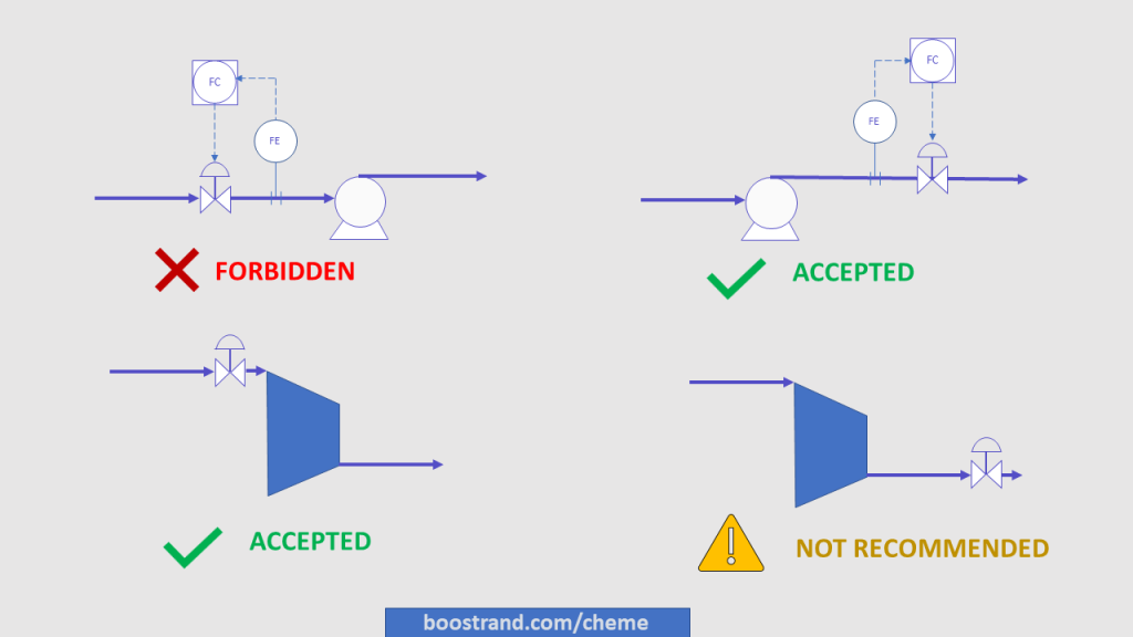
The function of process control is to ensure a stable operation of a specific system. However, implementing the control method in the wrong way can cause safety issues and equipment failure. For example, if we want to control the pump flow by placing the control valve on pump suction, this will cause pump cavitation. That’s why it’s always placed on pump discharge.
However, if we want to control the capacity of a dynamic compressor, it’s not recommended to place the control valve on the compressor discharge (discharge throttling) as it shall accelerate compressor surge and consume more power.
If we are using a constant speed-driven motor, then in this case it is more common to place the control valve on the compressor suction (suction throttling). Through suction throttling, the reduction in pressure due to valve throttling would lead to lower inlet density to the compressor, which would finally lead to less power needed to drive the motor, so this shall reduce the operating cost. You can check out how fluid physical properties and inlet conditions affect the compressor’s performance in this article.
In addition to the above, the negative effect of suction throttling with respect to compressor surge is less than in the case of discharge throttling. This is because any change in the resistance in the discharge system can quickly shift the compressor to the surge region.
What about Reciprocating Machines?
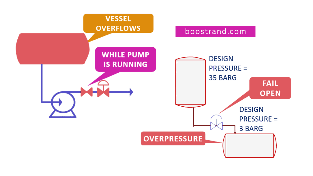
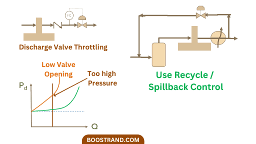
As a reciprocating pump or compressor gives a constant flow, throttling the discharge line be a great safety issue. This is because even if the valve was throttled or fully closed, the machine shall keep on pushing the same throughput, which shall increasing the pressure drastically. This can cause overpressure and failure in the discharge system.
That’s why in this case we control the capacity of the reciprocating machines through recycling or spillback lines, where the residual flow is recycled or sent to a safe location.
Tip 4: Can the Control Scheme Reduce Operating Cost?
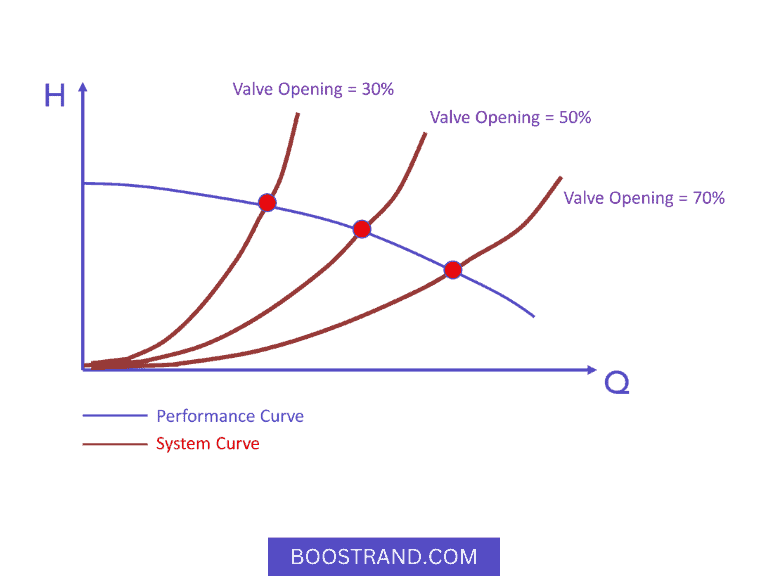
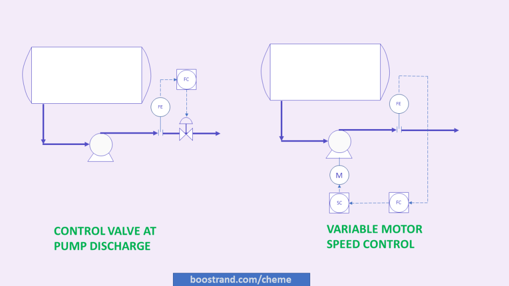
A famous example of cost optimization can be the capacity control of a pump. The most common method is that we have a flow element that sends a reading to the flow controller. The flow controller sends a signal to adjust the opening of the control valve on the pump discharge. Change in the control valve opening shall shift the system curve, which means a new operating point on the pump performance curve. You can check out the pump hydraulics course for more information on how the pump operation works.
However, this method consumes much power, especially for large pumps. Here comes another method which shall be through controlling the speed of the motor of the pump or compressor. This can be done by considering Variable Speed Drive (VSD) motors. They are also called Variable Frequency Drive (VFD) motors.
So when we need less flow on the pump discharge, the flow controller shall send a signal to the pump motor to reduce the speed of the motor. The lower flow requirements shall result in a new pump curve that gives much less head at this lower flow. At a lower head, the required motor power would be much lower. This shall lead to a significant reduction in the operating cost of the pump or compressor. This is a great advantage of VSD motors.
However, VFDs have a high fixed cost. In addition, they are complex and need heavy maintenance requirements, which doesn’t make them always as the favored method of control especially for pumps.
So here a process engineer should assess the impact of the control method on fixed cost of introducing VFD versus the operating cost savings that can be achieved when introducing speed control. In most cases, applying VFD wins for large pumps and compressors as these consume too much power, so they shall lead to significant savings.
In our compressor operation course, we have made a case study checking the change in different parameters against compressor operation and how it is shown on the compressor’s performance curve. One of these parameters was the change in compressor’s speed. We have plotted the effect of changing speed on different compressor performance figures, power was one of them for sure.
Tip 5: Do we need More than one Control Valve?
As we highlighted above when we talked about exchanger bypass control, the control valve operation and range can be highly affected by the control scheme. Sometimes, we may need a large control valve range between maximum and minimum operating cases, this may not be achieved by a single control valve. Another example can be when we need to balance between 2 destinations. So here we shall need a split range control.
Example: Split Range Control
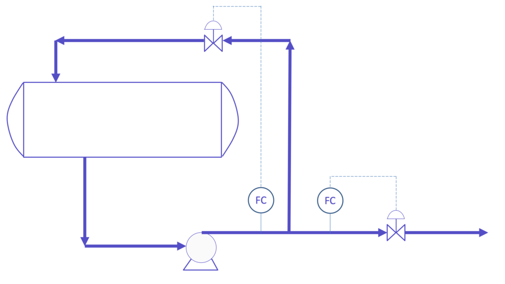
In split range control, we control the parameter using two final control elements. One of the famous examples of split range control is the pressure control of a vessel.
.png)
The above photo expresses a typical tower overhead drum. We have a vessel where its source of pressure is its inlet gas from the upstream partial condenser. The pressure here is important to control and adjust precisely as it affects the whole tower operation (check out Discover Basic Guidelines For an Effective Tower Operation). So to control the pressure of the vessel, we have two lines:
- The main line is where PCV 1-A is installed. The outlet gas pressure is controlled where the gas is then sent to the downstream facility, which can be a compressor suction for example. So when the vessel pressure is low, PCV-1A starts to close to build up the required pressure. Also if excess pressure starts to build up in the vessel, PCV-1A starts to open to reduce the vessel’s pressure.
- Now if too much gas entered the vessel that the compressor or facility downstream PCV-1A cannot handle, this would lead to an overpressure in the vessel. Here comes the job of PCV-1B, it starts to open and send the excess gas to the flare. Don’t forget that PCV-1A is now fully open.
Start your Career
Access Process Engineering Introduction Course
This is an example of split range control. We have two valves, the opening of one valve is normally varied against the variable to be controlled up to a certain limit. After this limit, the other valve starts to adjust while the first valve is fully open or fully closed. There are many other examples and forms. The type and application of a split range control depend on the criticality of the parameter to be controlled.
Tip 6: Do we need a Fast Response Control?
The dynamics of a control loop depend on the variable to be controlled. Some variables such as level or temperature have a slow response. So if a temperature controller sends a signal to the coolant valve to open, the effect of the valve opening on temperature is usually slower than the case if it was a flow controller. This is the same case of level control as well. One of the control configurations that are used to accelerate the response of temperaure and level control loops is the cascade control.
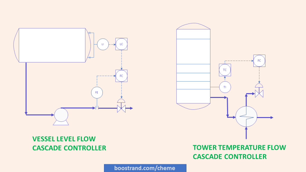
Example: Using Cascade Control
In the cascade control, the master controller, which is the temperature or the level loop, sends its signal to the slave controller, which is usually the flow controller. The flow controller adjusts the valve opening. This ensures a stable flow, which shall decrease the disturbance in the master loop, so we shall see less disturbance in level or temperature. In addition, the flow controller shall act as an early warning to the main loop as it shall reduce the disturbances in the downstream system (e.g. the cooling water or pump downstream pressure) which would have affected the main loop if no flow controller wasn’t installed.
Cascade control would also be used if we are concerned with both controlling the main variable (level or temperature) and the flow, while we have one final control element (control valve). The control logic in this case would adjust the priority for the more important variable to be controlled. Based on this logic the output is sent to the control valve.
Conclusion
So as we have seen, in order to determine the optimum control scheme, it’s important to have an understanding on how the system is expected to perform, what are the variables that have the priority to be controlled, the optimum control scheme that ensures a smooth operation, a good response and an optimized cost.
Start your Career
Access Process Engineering Introduction Course
Share this:
[…] creation of a PFD is typically based on the output of process simulation software. We have discussed plant simulation’s role in a project in the previous article. In a nutshell, process simulation involves using specialized software to model and analyze the […]