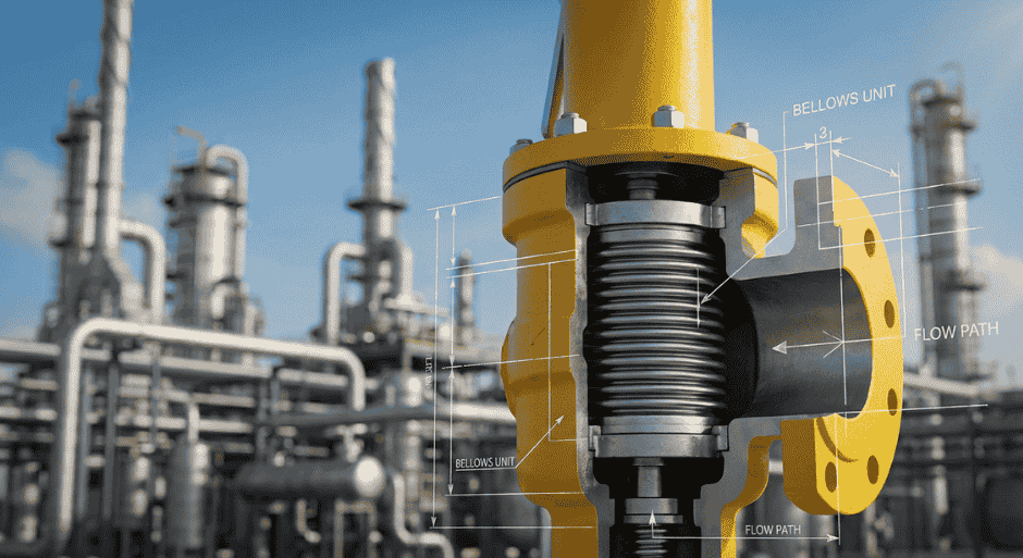
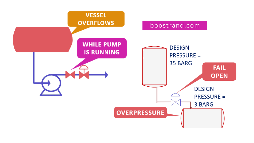
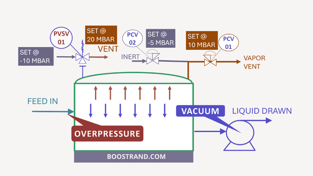
Control Valve failure is a very famous issue while operating a process plant, whether this was in refineries, gas plants, petrochemicals, water treatment, or other chemical industries. This is because a control valve is an essential component that exists abundantly in any process plant. Its failure shall have negative consequences on the operability and safety of the plant.
You can watch the content of this article in the below video, or you can skip the video and continue reading:
Main Function of a Control Valve
Final Control Element
Any plant will have control loops. Control loops will use final control elements that adjust the flow based on the process parameter to be controlled (you can check out this article talking about control scheme tips and how it works).
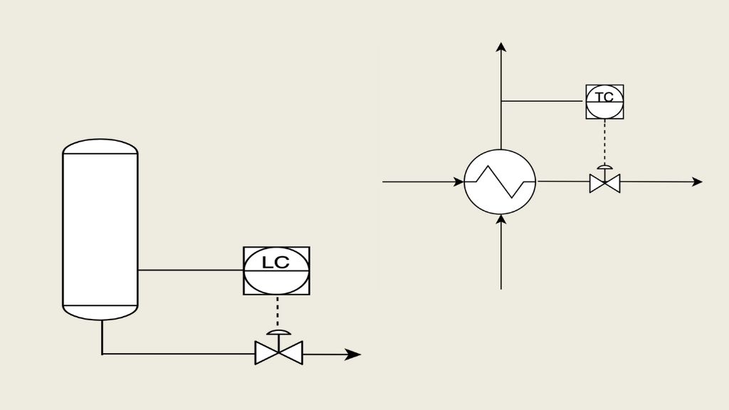
A control loop is composed of the following:
- A measuring device reading the parameter, e.g. a pressure or temperature transmitter
- The control system that receives the signal from the measuring device, processes the signal, and gives and output signal, e.g. DCS or PLC systems.
- The final control element that receives the output signal and take action, these are control valves in most cases but they can be other elements such as motors of rotating equipment for example.
So in any control loop, we will need a final control element to adjust a process parameter, whether it is pressure or temperature or flow or level,…etc.
Control valves represent the vast majority of final control elements. By changing the control valve opening, we can control the fluid flow, so we can finally reach the required set point of the controller.
Control Valve: Hydraulics, Characteristics & Sizing
Understand Control valve characteristics and hydraulics, estimate valve pressure drop and how to choose valve sizing cases based on controlling scenarios /cases
Adjust Pump Hydraulics
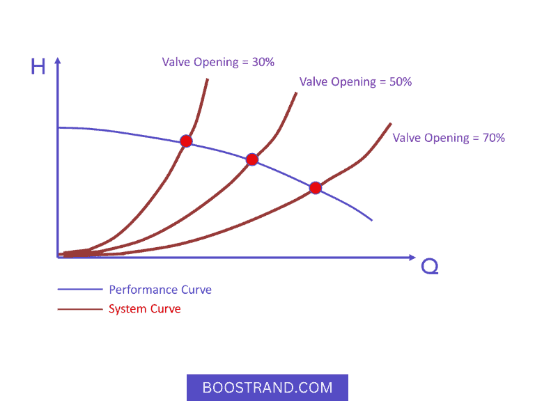
The control valve acts to adjust the operating point in the pump curve and how it shifts the system curve to intersect with the pump performance curve on the operating point we need.
If there is no control valve here, the pump will face the minimum resistance which means much more flow than expected and may even lead to the end of the curve which is not a good operating condition for the pump in many cases.
I have made a dedicated course for pump hydraulics where it plots the pump performance curve against the system curve and how the control valve on the discharge affects the pump operating point. You can check it out if you want more information about this subject.
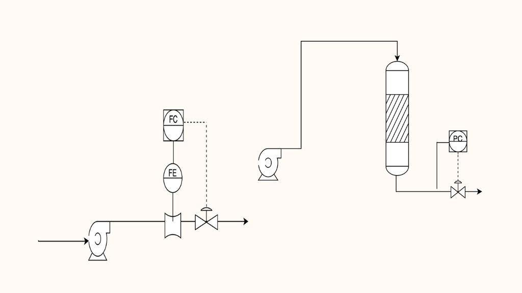
The control valve here doesn’t just adjust the flow, but also the reactor pressure. The pressure here is a much more important factor to control because it will directly affect the reactor conversion which shall lead to an off-spec product.
So here it is not just a matter of controlling the process against some disturbance, but it is more related to adjusting the system hydraulics. Still, the valves are working as a final control element receiving a signal from the flow or the pressure controller in their control loop.
Get low Temperatures through Joule-Thomson Effect
In a propane cycle, after we compress the propane gas, then cool it. It becomes a liquid under high pressure and around the room temperature. When we drop the pressure, the temperature falls immediately. This is done using a control valve.
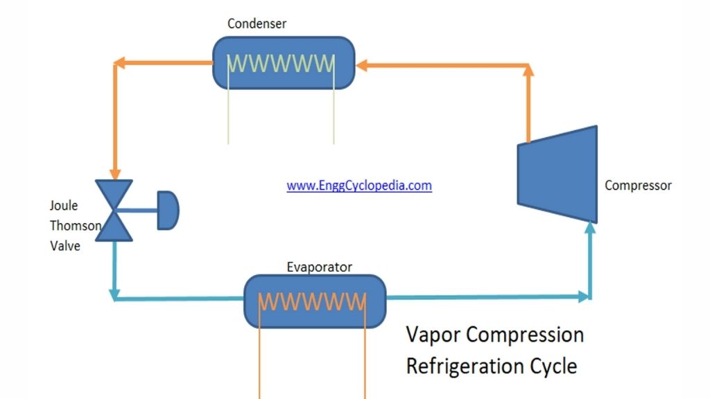
So here the control valve is an essential part of the process. We notice here that the control valve will still be used to control a variable and act as a final control element. This may be flow or level or temperature or pressure depending on the process itself.
Control Valve Failure
Instrument Air Supply cut
Control valves are equipped with actuators to move the valve stem upwards and downwards based on the signal received from the controller. Actuators are mostly pneumatic, which means that they drive power for the valve operation through pressurized air. This means that any plant would need an instrument air compressor and piping header to all control valves in the plant.
So what if, for any reason, the instrument air system fails? This means that there shall be no air supply to the valve and the actuator won’t work. So the valve would be either totally open or totally closed or that it stays in its last position. This means that we should be ready for this scenario.
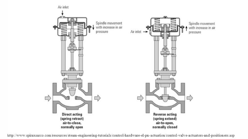
When the instrument air supply is cut, would it be safe that the valve is fully open or that it shall be fully closed or that it stays at the last position? This should be determined case by case. In the same plant, we may have valves with a fail open action, others with a fail closed action and sometimes failing in the last position. But at the end, we should ensure that the valve fail action shall be the fail safe position, which is the position that will be more safe for the plant.
Mechanical Failure
Instrument air getting cut is the most common cause of a control valve failure. However, there is also a probability of mechanical failure. So for example if the valve stem was stuck in the open or the closed position, this can still lead to an operational and safety issue.
Every control valve should be considered as being subject to inadvertent operation. (API 521 Fifth Edition)
So here in case of mechanical failure, control valve fail safe mode won’t be a protection against overpressure. So sometimes, we will even need an external protection for the upstream or downstream equipment to prevent any potential damage due to valve failure. This shall be covered in the below sections.
Equipment Protection
So if we want to ensure that the plant shall not have any safety issue if the control valve failed, we should consider the below:
Choose the suitable Fail action
So if the air supply was cut, the valve should be in fail safe position. This is a parameter that should be considered in the design phase. To choose the appropriate fail action, we should look at our system, would it be more safe if the valve opens or if it was closed?
Let’s take for example a pump case, we are showing here the pump control and protection in the P&ID drawing we have prepared before:
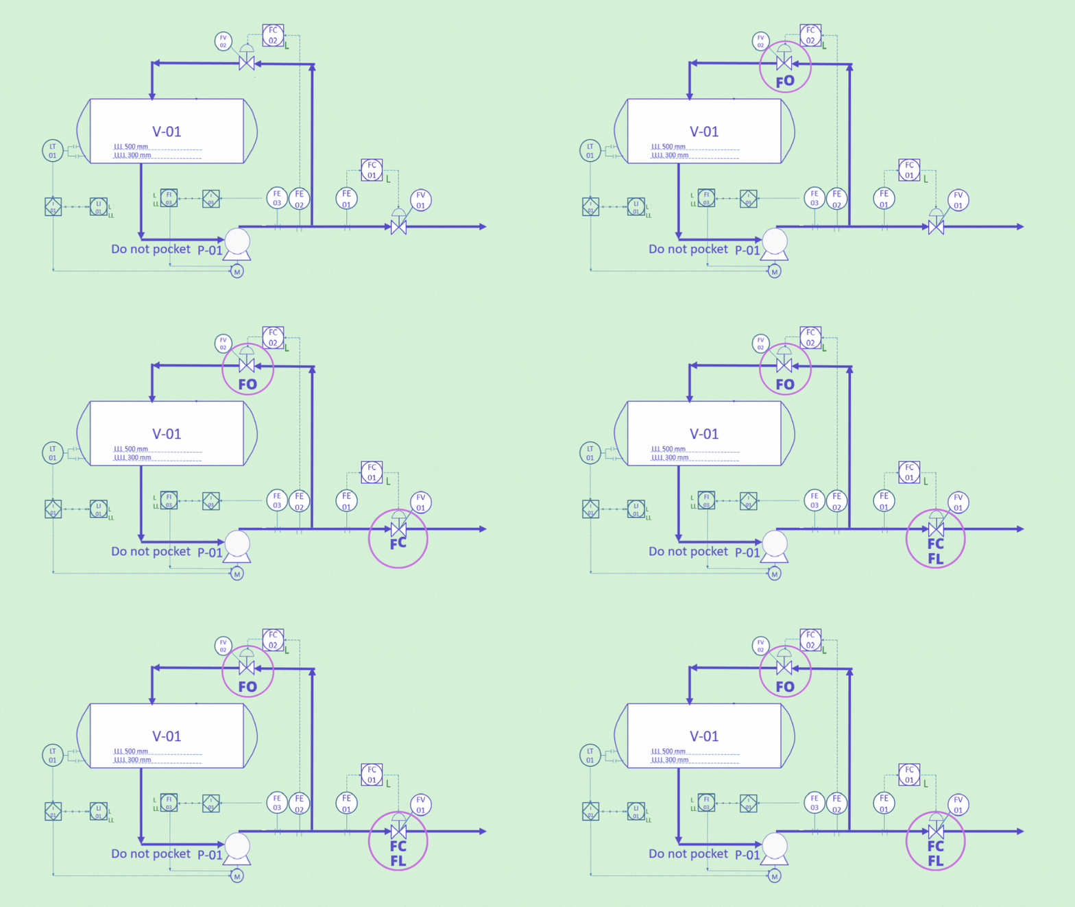
So we have two control valves here, we have a pump capacity control and a minimum flow control.
Pumps for Process Engineers
Learn how the centrifugal and reciprocating pumps operate, how to calculate pump main parameters as a chemical engineer
Fail Open
Now let’s start with the minimum flow control, this is placed to operate the pump at a flow which is more than its minimum flow.
When a pump works at less minimum flow, this can cause motor overload and damage to the pump. So we want to make sure the pump is well protected. If the air supply to minimum flow valve is cut, it would be better for the pump that the valve is at 100% opening than 0% opening. We would choose the fail action in this case to fail in the open position.
Fail Closed
But when we look at the capacity control, then the fail action would depend on the downstream process. For example, let’s imagine this situation:
- A pump is pumping the fluid to a distillation column or absorption tower
- The instrument air control valve air supply is cut.
- If the valve was left at 100% opening, this may cause disturbance in the tower, for example it may cause flooding (you can check out our article Discover Basic Guidelines For an Effective Tower Operation to understand more about how a tower is affected by flow disturbances).
So in this case, it would be better for the valve to be at 0% than to be at 100%. We would choose the fail action in this case to fail in the closed position.
But what about pump working at minimum flow? Well, we have a minimum flow controller, and if the air supply was also cut, then it will fail in the open position.
Fail Last (Drift Open or Drift Closed)
What if the downstream system won’t get much affected by the loss of operation of the control valve? And keeping the flow even if it is not exactly the required flow would help? This may be for example in offsite pumps that are pumping some feed to another unit or another plant. In this case, the valve can be in the fail last position.
This means that when the air supply to the valve is cut and its opening is 45%, the valve opening will still be the 45%. However, the fluid flowing will keep on pushing the plug either to the open position or to the closed position. So after some time, the valve will be fully open or fully closed. This would be specified as fail last drift open or fail last drift closed.
Let's go into P&IDs
P&ID journey: familiarize with P&ID details, anatomy, workflow, discover operation, maintenance & safety best practices
External Protection from Control Valve Failure
So we add a valve fail action to reduce the risks if the air supply was cut. But what if the valve experienced mechanical failure? In this case, we would need another protection to protect our equipment. So let’s talk about them in more detail.
Using Shutdown Action
Shutdown actions are one of the common protection methods in any process design. We have seen some of these examples when we talked about the preparation of pump P&IDs. Here we shall see another example.
Suppose we have this vessel in the below photo, which is operating at 3 barg. The bottom liquid from the vessel is then transferred to a tank which is operating at atmospheric pressure. The pressure is dropped through a level control valve LV-01 (Not FV-01).
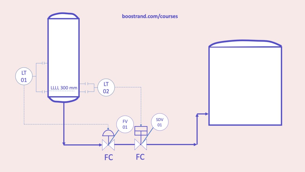
So what if FV-01 failed in the open position? This would mean that the vessel will be emptied from the liquid. After emptying the vessel from the liquid, the gas in the vessel starts flowing to the tank. This means that the pressure starts to rise, which shall cause overpressure in the tank that can cause the welding between the tank shell and roof to fail and gas exposure to the atmosphere. This can cause a safety and environmental disaster. This is called “gas blowby“.
So in this case, we shall need to stop the fluid to flow once the liquid level in the vessel reaches the low low liquid level, let’s say it’s 300 mm. This can be done by installing a level transmitter (LT-02) on the vessel that sends a signal to an on-off shutdown valve (SDV-01) to close it once the liquid level is 300 mm.
Install Pressure Relief or Safety Valve
In many cases, depending on shutdown protection may not be enough. Depending on the criticality of the overpressure consequences and the reliability of the instruments, or the emergency shutdown (ESD) system, which is usually studied in HAZOP and SIL analyses, we may need another layer of protection.
There is a higher level of protection to protect the system from control valve failure, which is to install a PRV, which would be a pressure relief valve (for liquid services) or PSV, a pressure safety valve for gas pressure. This would be set at a certain pressure, and once it reaches that pressure, it shall open and the pressurized fluid is either sent to flare for gases or another downstream system for liquids. In our article Pressure Safety Valves: An Essential Protection Against Overpressure, we talked in more detail about how a PSV works and the overpressure scenarios they address.
Sizing the PSV based on Control Valve CV
But how shall we choose the size of a PSV in this case? We need to know the maximum flow rate of gas that shall pass from the valve when the valve is fully open. This can be known through the control valve rated CV, which represents the valve Cv at 100% opening. This needs a separate control valve calculation. If you’d like to know more about control valves, you can check out our course related to control valve hydraulics, characteristics, and sizing.
Based on the outlet flow from the control valve, the PSV shall be sized to handle the flow rate when the valve is at its rated Cv. If the control valve is expected to pass a very large flow, we may add a mechanical stop to the valve to prevent the valve from reaching at 100% and consider a maximum opening at a less percentage. The mechanical stop however may affect the control valve operation. So optimization should be considered here.
Conclusion
So as we have seen, control valve failure should be well handled during the project design, we need to consider the proper valve fail action when the instrument air supply is cut. We should also consider how to protect our equipment and piping when the valve stem is stuck in an undesirable position.
Start your Career
Access Process Engineering Introduction Course
Share this:
[…] creation of a PFD is typically based on the output of process simulation software. We have discussed plant simulation’s role in a project in the previous article. In a nutshell, process simulation involves using specialized software to model and analyze the […]
