Transforming natural gas into a product that meets commercial standards and safety requirements involves removing various impurities. The first impurity that is commonly removed is related to acid gases. Acid gases are mainly carbon dioxide (CO2), and hydrogen sulfide (H2S).
This process of removing acid gases from natural gas is called gas sweetening. The most common gas-sweetening method is by using an amine-based solvent system. Here we explore the design complexities of an amine gas sweetening system, focusing on essential factors that should be considered in the process design of an Amine sweetening unit.
The Gas Sweetening Process
The amine gas sweetening process is a sophisticated sequence of operations involving several key components, each designed to fulfill a specific role:
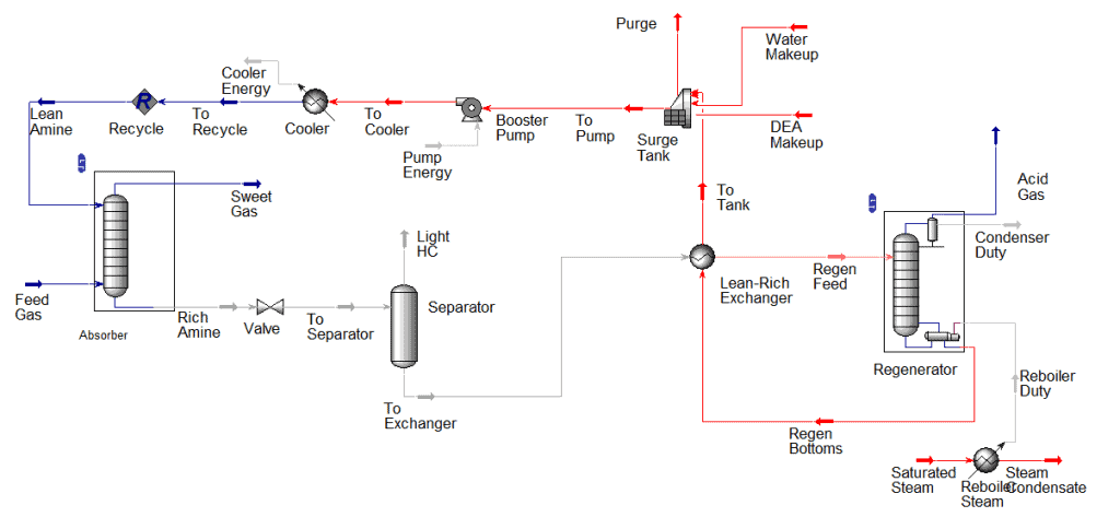
- Sour Gas Feed: Sour gas is introduced, containing H2S and potentially CO2.
- Inlet Filtration: Feed gas is filtered to remove particulates and liquid droplets that could harm the amine solution or downstream equipment.
- Amine Absorber: Sour gas contacts the amine solution in the absorber, where the amine absorbs H2S and CO2 (rich amine), allowing sweet gas to exit the top. This is our main product.
- Rich Amine: Amine loaded with acid gases (rich amine) moves to the regeneration section.
- Heat Exchanger (Rich-lean amine exchanger): Rich amine is preheated by hot, regenerated (lean) amine from the regenerator.
- Amine Regenerator: After being heated, rich amine is then introduced to Amine regenerator (stripper) to release the absorbed acid gases, which are then removed.
- Amine Tank and pump: To adjust amine concentration by adding the required make-up and pumping the lean amine back to the absorber.
- Lean Amine Cooler: Regenerated amine is cooled before recycling to the absorber.
Understanding each component’s role allows engineers to optimize the gas sweetening process. Now, let’s discuss the important considerations that should be studied when looking at any amine sweetening process.
Start your Career
Access Process Engineering Introduction Course
Remove Feed Gas Contaminants
Gas contaminants that need to be removed before the amine gas sweetening process include particulates, liquid hydrocarbons, aerosols, iron sulfide scales, rust, corrosion products, and other trace contaminants.
These can lead mainly lead to foaming in the contactor, which can cause several issues, such as amine carryover and off-spec sweet gas. In addition, it can lead to fouling, corrosion, and plugging issues that reduce the efficiency of the amine contactor.
These issues can cripple the operation in the contactor as it can lead to different issues in the tower hydraulics, which we have talked about when discussing design considerations for an efficient tower operation. In addition, foaming can also lead to a sweet gas rich with amine. In a previous post, we have talked about a foaming issue in a 3 phase separator, you can check it out if you like.
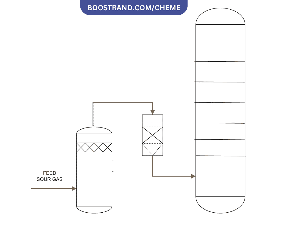
That’s why a filter removing small particulates up to 1 micron are used for most applications to prevent operational problems while balancing filtration costs. The optimal filter rating depends on the gas composition, system design, and equipment manufacturer recommendations.
Inlet Temperatures of Lean Amine and Sour Gas to the Absorber
The lean amine is kept at a higher temperature than the sour gas to prevent the formation of wet hydrogen sulfide or “sour water.” Wet H2S forms when the sour gas cools below its water dew point, causing moisture to condense and dissolve the H2S. This creates an acidic, corrosive solution that can lead to equipment corrosion and operational problems like foaming and fouling.
To avoid wet H2S formation, it’s common to introduce the lean amine to the contactor at a temperature higher than the temperature of sour gas by 5-10 C.
Amine Carryover
Amine carryover occurs when liquid amine droplets are entrained in the sweet gas leaving the absorber. This can lead to several operational challenges:
- Corrosion: In downstream equipment and pipelines.
- Product Contamination: Affects natural gas quality and downstream processing.
- Environmental Issues: Potential regulatory violations due to amine emissions.
- Increased Operational Costs: Additional amine replenishment required.
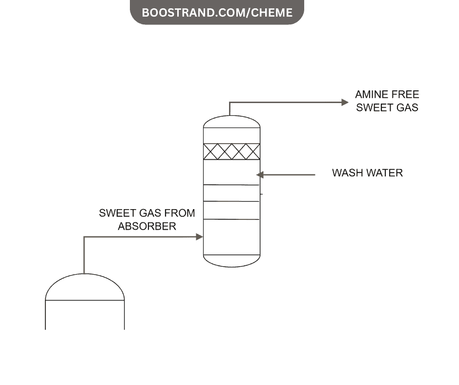
To mitigate amine carryover, different techniques are considered, such as mist eliminators, amine filtration, or washing with water. These measures ensure that the sweet gas is free of amine droplets, maintaining product quality and reducing corrosion risks.
Rich/Lean Amine Exchanger
The close temperature approach in a rich/lean amine heat exchanger allows the lean amine to be preheated to near the temperature of the rich amine exiting the absorber. This does 2 things:
- It optimizes the absorption process by ensuring the lean amine is sufficiently cool to efficiently absorb acid gases from the sour gas.
- It also reduces energy usage in the regenerator by minimizing the amount of additional heating needed to reach the regeneration temperature.
The close temperature approach creates synergy between the absorption and regeneration sections and is a key factor in the overall energy efficiency of the process.
The issue here is that a close temperature approach would commonly lead to a large exchanger or more than one shell and tube exchanger in series. That’s why shell and tube exchangers may not be the most suitable option for this service.
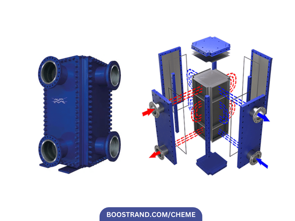
Plate and frame heat exchangers are well-suited for amine service because of their high heat transfer efficiency in a compact design, ability to achieve close temperature approaches, ease of cleaning, modularity, and low hold-up volume.
They are typically made of corrosion-resistant alloys and have specifications tailored to amine service, like corrugated plates to induce turbulence. The flow configuration maximizes heat recovery between the streams.
Amine Degradation
The maximum outlet temperature for regenerated amine is typically 120-140°C. Exceeding this range risks amine degradation which can lead to foaming, fouling, corrosion, and reduced gas absorption capacity.
The specific maximum temperature depends on the amine type, concentration, inhibitors present, and system pressure. To avoid degradation, the heating medium temperature, usually steam, must be optimized based on steam quality, reboiler design, precise control mechanisms, and maintaining low heat flux.
That’s why it’s highly important here to consider proper control of the heating medium inlet temperature in order to ensure that it won’t lead to a high skin temperature in the reboiler, which can cause degradation in the amine solution.
Start your Career
Access Process Engineering Introduction Course
Rich Amine Corrosion
Rich amine solutions are corrosive, particularly after absorbing acid gases. They tend to react with the steel in the pipe and form a layer. This layer shall prevent further corrosion, however it is subject to erosion at high velocities, which shall lead to further corrosion.
To manage this, API dictates a velocity limit of less than 6 ft/s is commonly set for amine in pipes and equipment, reducing the risk of erosion, which eventually means further corrosion. In our pipe sizing course, we have talked a lot about how to choose the correct pipe size based on velocity limits.
Conclusion
The amine gas sweetening process is a complex interplay of chemistry, thermodynamics, and engineering design. By addressing each aspect, from filtration and heat exchange to managing amine carryover and corrosion, engineers can design systems that are efficient, reliable, and safe. Amine gas sweetening plants can thus meet product specifications and environmental regulations, ensuring the natural gas produced is clean and suitable for end-users and downstream applications.
Start your Career
Access Process Engineering Introduction Course
Share this:
[…] creation of a PFD is typically based on the output of process simulation software. We have discussed plant simulation’s role in a project in the previous article. In a nutshell, process simulation involves using specialized software to model and analyze the […]
