PSV Sizing Guide: How to Calculate the Backpressure Correction Factor (Kb)
Pressure Safety Valves (PSVs) are the final line of defense against catastrophic overpressure events. While a PSV’s…
Proper venting of atmospheric and low-pressure storage tanks is critical to prevent tank damage or failure that could lead to safety and environmental incidents. API Standard 2000, “Venting Atmospheric and Low-pressure Storage Tanks”, is the industry consensus standard that provides requirements and guidance on properly designing normal and emergency tank venting systems. The standard applies to storage tanks in petroleum, petrochemical, and chemical services.
In this article, we shall go through the considerations listed in the 7th edition of API 2000 that a process engineer should pay attention to when designing a storage tank. So let’s start!
Venting a tank is a very critical function that we should take into account. This is because tanks are very sensitive to overpressure and to vacuum. If you recall in a previous article Understand the Basis to Select Proper Storage Tank Type when we talked about how the fluid vapor pressure highly affects the tank type and how a normal API 650 tank is expected to operate at a very low overpressure.
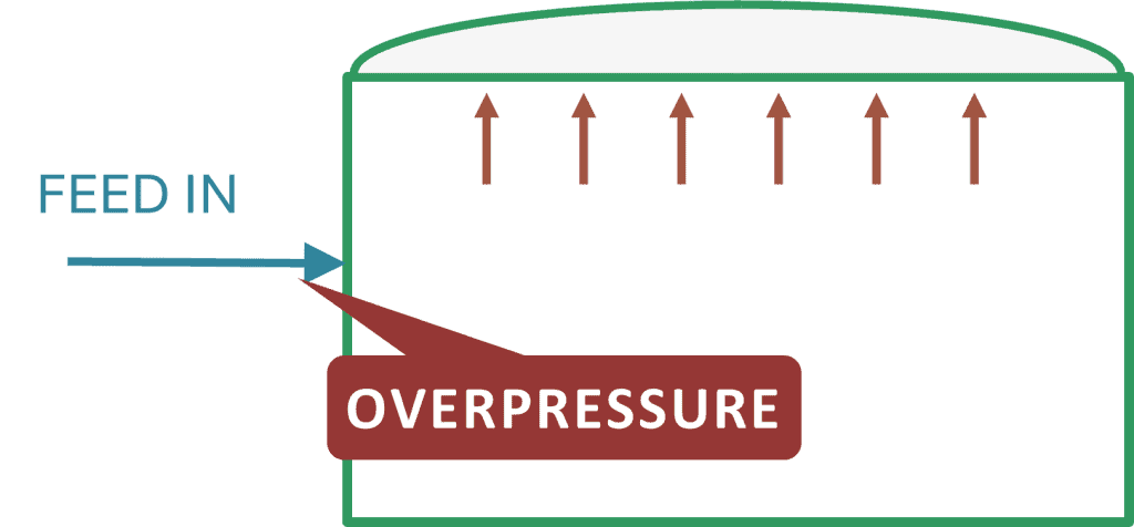
That’s why atmospheric tank operating and design pressures are in millibars. We are dealing with a very narrow pressure range. If the vapor accumulates in the tank vapor space to a point causing overpressure, this can lead to damaging the tank welds, causing a failure in the tank.
This is not just related to overpressure. We should also consider the vacuum in the tank as a critical scenario. As the tank is expected to work at design pressure, the occurrence of a vacuum can lead to tank collapse, which means tank failure as well.
So here we are dealing with a piece of equipment that is very delicate to changes in pressure. This needs care when designing the venting system of the tank. We should ensure that the inbreathing system protects the tank from excessive vacuum. On the other hand, the outbreathing system should ensure that the tank is protected from overpressure.
Changes in tank pressure can be due to several scenarios that occur during normal operation. These may appear as insignificant values for a pressure vessel. However, when we talk about atmospheric or low pressure tanks, these can lead to tank failure. These scenarios can be:
Become a Professional Process Engineer, discover process engineering career, role, activities and common practices with access to most of the courses here.
These are frequent conditions. So they should be dealt with through normal control systems such as inbreathing and outbreathing valves or open venting. If these systems cannot handle severe changes, a pressure vacuum safety valve is commonly installed to address excess pressure or vacuum. So let’s go through both of them.
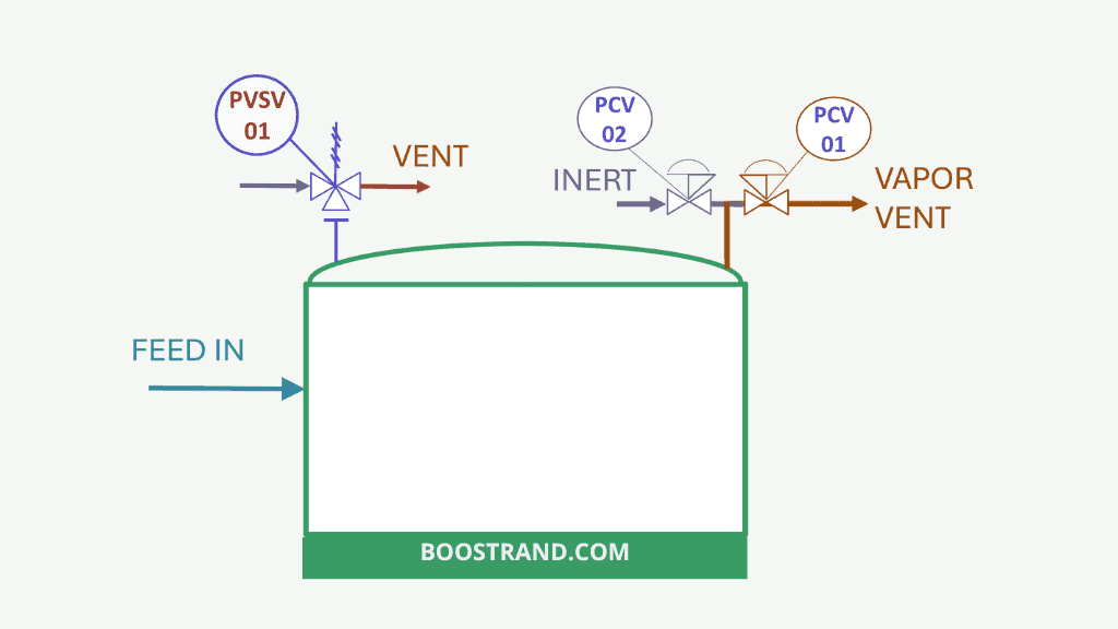
This is carried out through a pressure control system or pressure regulators. The breathing system is composed of:
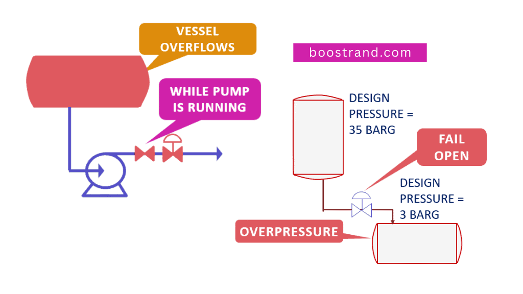
Now what if the breathing system fails? For example, an inbreathing or outbreathing valve can fail in the open or closed position. For example, if the blanketing valve fails in the open position, this shall introduce too much inert gas into the tank, causing overpressure. On the other hand, if the valve fails into the closed position, this can cause vacuum in the tank, and vice versa for the outbreathing valve.
So here the tank venting control is efficient in the normal operation. However, it cannot be the sole system to rely upon as it can be a source of overpressure or vacuum in case of failure. Here comes the importance of the next layer.
Pressure vacuum safety valves employ a weight-loaded mechanism that counteracts the pressure or vacuum forces. When the internal conditions reach the set thresholds, the force acting on the valve overcomes the spring or weight, causing the valve to open in the relevant direction, either to introduce air or to vent excess pressure.
Here comes the role of pressure vacuum relief valves. These valves can act either as the normal venting device, or as an additional layer in case the blanketing control failed. They are mechanical devices, so they are much more reliable. However, it’s always preferred to use a control system to avoid causing the PVRV opening continuously whether for breathing in or breathing out, which can cause damage in the long run and excessive air ingress.
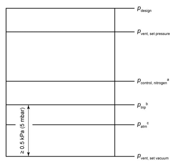
That’s why the common approach is to use blanketing / venting control or regulators to adjust tank pressure at low pressure or vacuum set points. If the pressure in the tank starts to go beyond these set points, the PVRV shall start to act and restore the tank to its allowable pressure range.
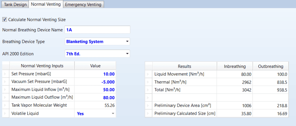
The first step in designing a tank venting system is to determine the required venting capacity for both normal operations and emergency conditions. In order to define the venting capacity, we shall need to analyze each scenario. API 2000 provides equations and tables to calculate the required venting capacity for inbreathing (air flowing in) and outbreathing (vapors flowing out) during normal operations. You can find them in section 3.3.2 and in Annex A.
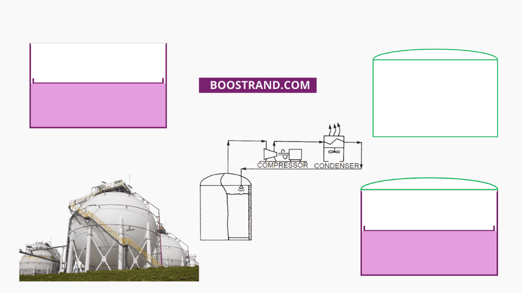
As stated above, thermal effect is caused either by a decrease in the vapor space temperature, such as cooling at night leading to vapor condensation or due to solar heating during the day, leading to a vapor space temperature increase, which means liquid evaporation.
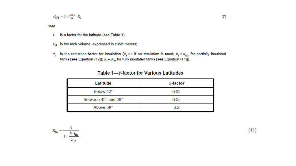
API 2000 7th edition introduced two rigorous methods to calculate the required inbreathing and outbreathing capacities for thermal effects, one in section 3.3.2 and the other in Annex A. These methods require evaluating heat transfer at extreme conditions, ambient temperature swings, solar radiation, and tank paint properties among other parameters. The required capacity depends on:
When liquid filling of the tank is carried out, we shall need to calculate the flow rate of vapor/gas being displaced. This shall result in a volumetric flow rate of the gas equal to the liquid filling rate multiplied by a factor.
This factor shall depend on whether the liquid is non-volatile (vapor pressure < 5 kPa) or volatile (vapor pressure > 5 kPa).
If the fluid is flashing, which means that there is already vapor at operating conditions, the outbreathing line should be sized based on an equilibrium calculation, which shall lead to a large outbreathing system.
For tanks that are only emptied and not refilled, the inbreathing during emptying sets the normal vent size. This is commonly equal to the flow rate of the gas volumetric flow rate equivalent to the volumetric flow rate of the pump drawing liquid from the system.
The total normal venting requirement is the sum of the thermal breathing and the filling/emptying capacity, unless the operations are conducted separately. By calculating the required flow rate of inlet or outlet gas in case of thermal effect and due to liquid movement, we can calculate the size of the control valve, regulator, PVRV, in addition to their inlet and outlet piping.
So we talked above about the normal changes in pressure that can cause overpressure or vacuum in the tank. What about the emergency conditions or critical scenarios? These can be:
Pressure Safety Valves (PSVs) are the final line of defense against catastrophic overpressure events. While a PSV’s…
Ensuring the proper protection of a chemical or oil and gas plant from overpressure is…
As we discussed in a previous article, Pressure Safety Valves (PSVs) play a crucial role…
Introduction In any oil facility, gas plant, or chemical or petrochemical plant, pressure safety valves…
These are supposed to be upset conditions. The pressure vacuum safety valve may deal with them. However, in case the emergency venting rates are very excessive, other devices would need to be in place such as emergency hatches or rupture discs or frangible roofs.
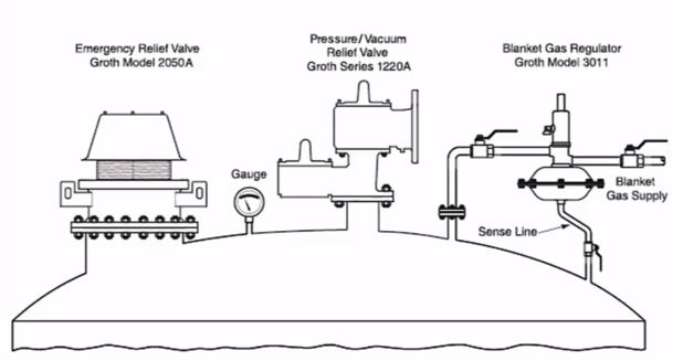
So in order to ensure that emergency venting is addressed, emergency venting devices should be in place. They can be:
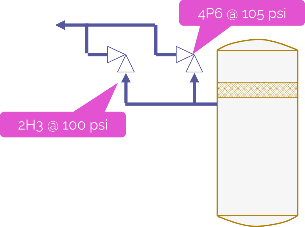
The emergency devices should be sized to address the maximum emergency vent load. For tanks that require large emergency venting capacity, multiple PV valves are often installed on separate nozzles.
For even larger loads, PVSV would be enough. As rupture discs and frangible roofs a non-reclosing devices, which means it can be used once, they are not the preferred method for protection. That’s why emergency hatches are the most common device used as a final protection against external fire.
Blanketing is typically carried out by an inert gas to avoid the formation of a flammable atmosphere in the tank. This inert gas can be Nitrogen or some other gas that is available in the plant such as fuel gas for example. This means that we shall need a utility system to provide the tank with the required inert gas flow rate at a suitable pressure.
The destination of the tank vent can either be:
Flame arrestors are devices installed on vents that prevent the propagation of a flame from an external ignition source into the tank. They use a matrix of metal ribbons or expanded metal to quench the flame front. Flame arrestors add pressure drop to the vent flow, so the vent size must account for this restriction.
Flame arrestors are used on tanks with flammable vapor spaces to mitigate an internal ignition event. They may be integral with the PV vent or a separate device. The flame arrestor must be designed for the required flow rate and the fluid properties. Dirt and debris can plug the flame cell matrix, so periodic cleaning is required.
The inlet and outlet piping connections to venting devices must be carefully designed to ensure a smooth venting and blanketing operation. Some of these piping considerations are:
Become a Professional Process Engineer, discover process engineering career, role, activities and common practices with access to most of the courses here.
Even a well-designed tank venting system is only effective if it functions reliably. Proper inspection, testing, and maintenance of venting equipment is critical to ensure it will operate as intended when needed. Some key considerations include:
Keeping detailed maintenance and test records allow any deteriorating trends in venting capacity to be identified. Faulty vents should be promptly repaired or replaced.
Adjusting the tank pressure is a deep subject that needs a thorough study in order to decide the proper venting and blanketing devices and requirements. API 2000 is an essential source for determining the expected scenarios of vacuum and overpressure a tank can face and how to determine the capacities of venting devices.
Access Process Engineering Introduction Course
[…] creation of a PFD is typically based on the output of process simulation software. We have discussed plant simulation’s role in a project in the previous article. In a nutshell, process simulation involves using specialized software to model and analyze the […]