Process design is the cornerstone of any successful project. That’s because a process engineer plays a crucial role in creating efficient, safe, and sustainable processes.
Through a deep understanding of chemical engineering principles, a process engineer can deliver an optimized and sustainable process design. This can be seen from the start of the project when carrying out process simulation, specifying the role of each piece of equipment in the process, optimizing equipment sizing, and ensuring that the plant operates safely and efficiently.
In this article, we shall go through these activities and documents developed by a process engineer and how each of these affects the overall project workflow.
If you’d like to see the content of this article as a video, you can check out our YouTube video. Otherwise, you can continue reading this article:
Context of a Typical Engineering Project
In the chemical, oil and gas, or petrochemical industry, project execution is a complicated process that requires the combination of the following:
- Applying engineering common practices
- Optimizing current resources, not just budget and timeframe, but also making use of available utilities and considering existing engineering constraints.
- Proper communication between project stakeholders and engineering disciplines

Applying Engineering Common Practices
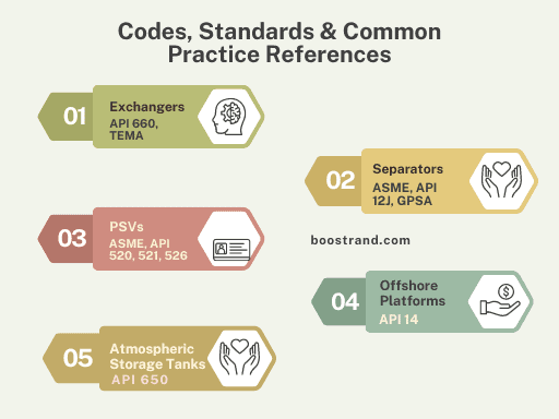
A process engineer should be aware of the common practices to be followed in the process design. This can be related to the operating pressures and temperatures, guidelines and sizing criteria of equipment and piping, considerations for easy operability and maintainability, and so on.
Common practices can be found in different standards and previous experience. We see these practices in codes and standards like ASME, API, TEMA, and many other standards. These can also be the standards of specific companies such as Shell, Bechtel, Aramco, among others. These can also be vendor practices such as Koch-Glitsch or Sulzer for tower tray design.
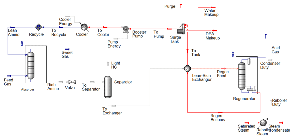
We have already talked about lots of them through this website, you can see for example some practices that are followed in the Amine unit, other practices that are followed in pipe sizing, separator sizing, or choosing shell and tube exchanger TEMA type, and many other articles.
Optimizing Resources
When carrying out the process design, we should consider the available resources. We know that the budget always governs the whole project. Although many practices should be applied regardless of the budget, there are cases where criteria may be waived due to budget constraints.
For example, some plant owners may specify minimum dimensions or sizing requirements for a piece of equipment. This would lead to a larger size, which means a higher cost. However, if there is no real need for this requirement and there is a restriction in the budget, then this requirement may be neglected.
When we talk about time, this can also be an important constraint. If we need the project to be executed as soon as possible, this may lead to special orders, which means a higher cost in order to achieve the required project completion dates.
The resources are not just related to time and money. There are also engineering restrictions. For example, in offshore projects, there are very high restrictions with respect to the plant area and equipment weights. So in this case the minimum sizing is the highest priority. If we are restricted by the use of some utilities such as cooling with air instead of water because no cooling water system is available, then we cannot use water coolers in this case, and so on.
Communication between Disciplines and Project Stakeholders
A process engineer isn’t working alone. He should understand the project parties and their requirements and constraints. These can be external parties and internal parties.
External Parties
When we talk about a typical project, we should take other stakeholders into consideration. If the process engineer belongs to the engineering company or contractor, he should understand the role of other parties. These can be:
- The client, who can be an investor or the plant owner
- Vendors for different plant components
- Construction contractors and other service providers
A well-executed project should ensure the proper coordination between all these parties. That’s because each has its requirements and interfaces. That’s why there are detailed contracts that limit the boundaries between the engineering company and all these stakeholders. Failing to have proper coordination shall lead to severe consequences that will cost a lot.
Process Engineering Masterclass
Become a Professional Process Engineer, discover process engineering career, role, activities and common practices with access to most of the courses here.
Internal Coordination
An engineering company is composed various disciplines. These can be technical disciplines such as piping, civil, mechanical, electrical, and instrumentation engineers, or these can be project management, planning, and cost control engineers. Each of these has its constraints and requirements as well.
A process engineer should have a deep understanding on how his design affects other disciplines. In addition, he should be aware of the consequences of their feedback or requirements on the current design. The engineering team should have an efficient information transfer between disciplines to ensure that all plant components are delivered properly fulfilling their design requirements.
So here, effective project management is essential to maintain the safety, quality, and reliability of chemical plants and other process facilities. A process engineer must not only have a strong foundation in core engineering principles, but he should also be adept at managing resources, evaluating risks, and making informed decisions that contribute to the overall success of a project.
Basic Deliverables of Process Design Package
So as we see, a process engineer is required to evaluate the main requirements for the plant to achieve efficient and safe operation. In addition, he should carry out sizing activities for various plant components. This data is needed to proceed with downstream detailed engineering activities carried out by other engineering disciplines, the procurement of material, and site construction activities.
How shall all this data be delivered? This is done by the following:
Carrying out the required activities
Usually, the process activities are internal calculations or software runs to determine the process and sizing requirements. Their output is reflected in other documents. For example, the output of process simulation is reflected in the process flow diagram (PFD), the output of pipe sizing is reflected in P&ID or the line list, the sizing activities output is reflected in equipment datasheets,…etc. However, activities are not delivered to other engineering disciplines. Still, they may be reviewed by the client or third-party consultants to ensure they are carried out properly as they can lead to unoptimized processes or undersized equipment.
Providing the required documents
The documents reflect the official channel between a process engineer and the client or other engineering disciplines/vendors. They reflect the output of the design whether by different activities or agreements with the client or vendors. All documents are considered part of the official project schedule and their level of accuracy depends on the project phase being in an early stage or a late stage.
So let’s go through the common activities and documents provided by a process engineer, discover how they are used by others, and see how they affect the whole project.
Process Engineering Masterclass
Become a Professional Process Engineer, discover process engineering career, role, activities and common practices with access to most of the courses here.
Activities Carried out by a Process Engineer
a. Process simulation and its importance
Process simulation is the most important activity that is carried out by a process engineer. This is because predict how a chemical process will behave under various conditions and to optimize the process design to improve its efficiency and profitability. Based on process simulation output, we get the main flow rate, fluid compositions, physical properties and operating conditions that shall be used in downstream sizing activities. That’s why the optimization of process simulation is highly important.
Process simulation is carried out by dedicated software such as Aspen Plus, Aspen HYSYS, and PROII. The key outputs of process simulation are:
- The flowsheet provides a visual representation of the process and its various unit operations. It shows the direction of material flow, as well as the physical and chemical changes that occur as the material passes through each unit operation. The simulation flowsheet can be considered the base on which the process flow diagram (PFD) will be created.
- The Heat and Mass Balance (HMB): Output HMB tables are one of the main deliverables that are officially issued by a process engineer. It’s used to reflect the required flow rates, fluid properties, pressure and temperature for each portion in the process. Based on HMB, we can start sizing equipment and piping and add process requirements for the instruments.
In summary, based on process simulation, the whole plant shall be designed. That’s why care should be taken to ensure a smooth process that considers optimizing fixed and operating costs while achieving product specifications. You can check this article if you’d like to know more about process simulation’s role in a project.
b. Equipment Sizing
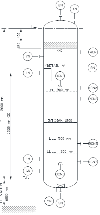
Equipment sizing is another critical activity that should be well carried out. This is because it ensures that process equipment is appropriately sized to handle the required throughput and operating conditions. This includes the sizing of reactors, heat exchanger thermal design, distillation/absorption column internal design , separators, and other process equipment.
Proper equipment sizing should consider the following:
- The equipment is doing its function efficiently based on the feed conditions and flow rates. So the exchanger can achieve the required duty and get the required outlet temperatures, a column or a separator can get on-spec product with the least impurities,…etc.
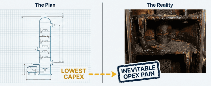
- Minimizing capital cost by optimizing equipment dimensions and operating costs through minimizing utility and power consumption. For example, a distillation column needs optimization between the number of stages, which reflects the fixed cost versus the reboiler and condenser duties, which reflect the operating costs due to the consumption of heating and cooling media.
- Proper operability of equipment and its ease of maintenance by choosing the most suitable type. For example, fixed tubesheet heat exchangers or bubble cap trays are not the best choice for fouling fluids as fixed tubesheet heat exchangers cannot be removed for cleaning and bubble cap exchangers shall be easily plugged.
Through equipment sizing activities, a process engineer can give the main equipment dimensions and requirements. Based on the sizing output, the equipment data shall be added in the relevant datasheet. This datasheet shall then used by the equipment manufacturer, mechanical, civil engineers, and other engineering disciplines. If a piece of equipment needs some utilities or some power, then this should be considered as well by the concerned disciplines.
So if the equipment sizing activity wasn’t carried out well, the downstream manufacturing and engineering activities can lead to a piece of equipment that is not performing its job. This can cause severe issues. So sizing should be taken with high care.
c. Line Sizing
Line sizing is another essential activity in chemical engineering projects, which involves determining the appropriate diameter for the piping that transports fluids throughout the process. In our article Pipe Sizing Criteria and Calculation Procedure for Process Engineers, we have talked in much more detail about pipe sizing. It’s important for several reasons:
- Proper line sizing ensures that flow velocities are maintained within acceptable limits, minimizing the risk of erosion and corrosion to the piping system.
- A pipe size with a reasonable diameter shall give a low-pressure drop. Hence it contributes to the hydraulic balance of the system.
- It helps optimize the energy requirements of fluid transport, reducing pumping costs and improving process efficiency.
- For two-phase fluids, proper pipe size shall reduce the probability of slug formation, which shall help reduce vibration stresses on the pipe, which can eventually lead to pipe rupture.
So here, a process engineer is responsible for providing the correct pipe size that shall help ensure the hydraulic balance and system efficiency. The pipe size should be well reflected in the P&ID and in the line list as these are the official documents used by piping engineers to know the required pipe size.
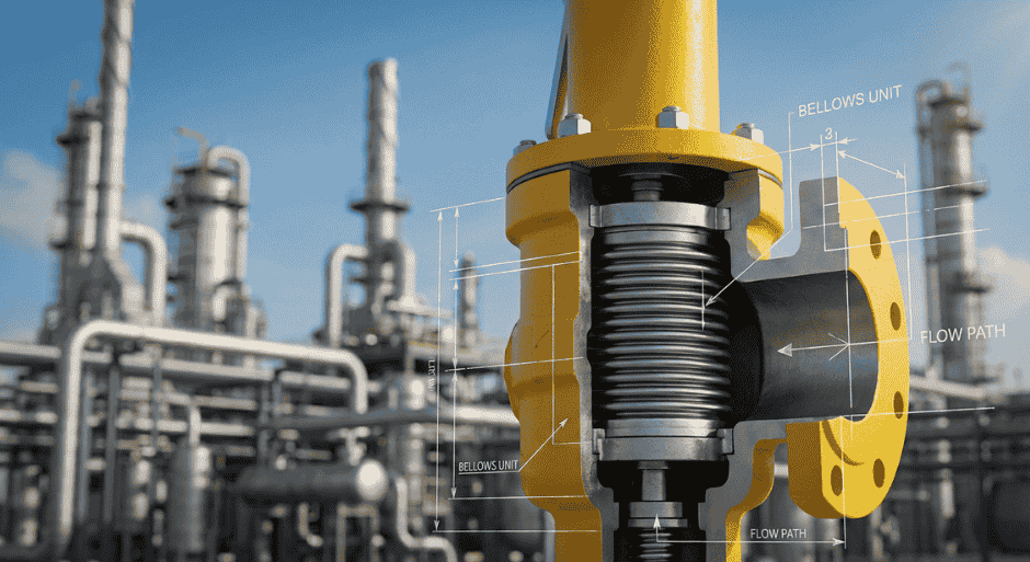
d. PSV Sizing
Pressure Safety Valve (PSV) sizing is a critical aspect of process safety in chemical engineering projects. PSVs are designed to relieve excess pressure in process equipment and piping, preventing catastrophic failures and ensuring the safe operation of the plant.
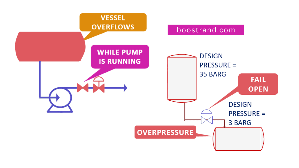
Proper PSV sizing is essential to ensure that the valve can adequately relieve the required flow rate under various overpressure scenarios, such as equipment overfill, fire exposure, blocked outlet conditions, …etc.
If you’d like to know more about how a PSV sizing works, you can check out this article. The PSV sizing data are commonly reflected in the datasheet. However, in order to ensure that they are well placed and installed, their data should be also reflected on the P&ID in order to perform a proper equipment protection analysis. The importance of this analysis is highly manifested during HAZOP assessment.
e. Hydraulic Calculations and Flare Study
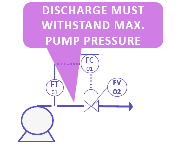
Hydraulic calculations are necessary to evaluate the performance of fluid transport systems in chemical engineering projects. These calculations involve the analysis of pressure drops, flow rates, and other parameters to ensure that the process operates efficiently and safely. In our courses related to pipe sizing, pump, control valve hydraulics, sizing and characteristics, we have gone through how the pumps and control valves affect the whole hydraulic balance of the system.
For example, if we want to size the pump properly, get its required differential head and NPSH, and hence estimate the elevation of the upstream vessel, we would need to carry out a detailed pump hydraulic calculation analyzing the pressure drops in both suction and discharge. If we want to properly size a control valve and estimate its pressure drops at maximum and minimum flow rates, this would need another hydraulic calculation, and so on. The output of these calculations should be reflected in pump and control valve datasheets in order to be considered by the manufacturers.
Hydraulic analysis is also needed for the relief system. The flare study is a specific type of hydraulic calculation that focuses on the design and performance of flare systems, which are used to safely dispose of excess hydrocarbons and other process gases during emergency situations. Through the flare hydraulic analysis, a process engineer can calculate the proper size of the flare header and subheaders to be considered in the P&ID and finally in the piping material takeoff.
f. Determine design conditions
Here, we are talking about design pressure and temperatures. Design conditions are different than the operating conditions. If a vessel is expected to operate at 10 barg, then its operating pressure is 10 barg. However, if something wrong went into operation and the pressure was raised, then there is a pressure on which the vessel is mechanically designed to withstand, let’s say, 15 barg. The same applies to temperature. In our P&ID course, we have gone through how to ensure that the system is inherently safe by considering proper design pressure and temperature.
A process engineer is responsible for determining the expected upset scenarios for each component, whether it’s a pipe, piece of equipment, or instrument. Based on the upset scenario, we can determine the design pressure and temperature.
Considering the proper design conditions is of high importance. These conditions shall be reflected in different equipment datasheets and in the line list in order to be considered by mechanical engineers and equipment manufacturers. Based on the design conditions, mechanical design, stress analysis, and structural calculations are carried out. If these are based on improper conditions, the relevant component will be subject to failure. That’s why this activity should be taken with great care.
Essential documents for project execution
a. Process Design Basis
The process design basis is the first document typically issued in a project. It should contain all the information necessary to start the design. These can include the below:
- Scope of the project and the role of the engineering company within the plant. Defining the scope is highly important to have a clear agreement on the responsibility of the engineering company.
- Feed Specifications: mainly the required capacity and the composition, pressure, and temperature of the feed.
- Product Requirements: for example, if this is a sweetening unit, then we should define the target sulfur content (typically from 4-7 ppm). This is the figure based on which we say that the unit is doing its job. If this is a compressor, then we should specify the pressure at delivery, and so on.
- Available utilities, drain and relief systems: The new project is expected to use cooling water, electricity, or other systems. Shall we use the existing systems or consider adding new utility systems to serve our project? The design basis should specify the utilities to be used, their capacities, operating and design conditions.
- Site conditions: such as ambient temperatures, mean sea level and wind speed, and other weather and topographic conditions that shall be needed in our design.
- Design criteria: The criteria based on which we shall size different equipment. This may be in a design basis or in a separate document.
So here, we see that the BoD (Basis of Design) is highly important to define what is exactly required in the project. This shall help ensure that all project parties have the same understanding on the scope and objective of the project.
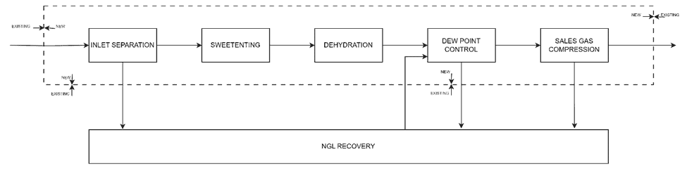
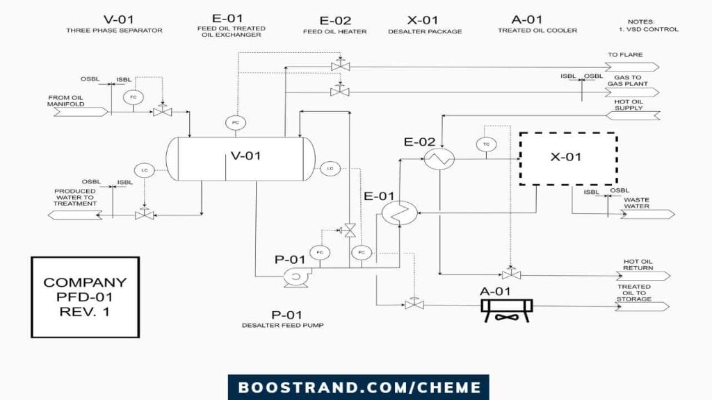
b. Process Flow Diagram (PFD)
A Process Flow Diagram (PFD) is a schematic representation of the overall process, depicting the main process units, equipment, and piping, as well as the flow of materials and energy throughout the process. In addition, a PFD is expected to show the basic control schemes of the plant.
A PFD also shows all equipment, lines, and control loops in addition to normally no flow lines that are not shown in process simulation. For example, relieving lines to flare that are used to control pressure, tank blanketing, ..etc. A PFD is also expected to highlight all operating modes.
c. Piping and Instrumentation Diagram (P&ID)
Now, based on the PFD, a P&ID is developed. A Piping and Instrumentation Diagram (P&ID) gives more detailed representation of the process. Through the P&ID, The P&ID includes detailed information on the following:
- Pipe details such as size, material, class and insulation requirements
- Manual, control and shutdown valves
- All instruments and PSVs
- Interconnection of process units and control loops
- All equipment nozzles
- Detailed destination of piping and tie-ins with existing systems
- All drain and utility lines
- Equipment isolation and maintenance requirements
- Plant protection through interlocks
So as we see, the P&ID shows most of the details in a project. That’s why it is considered as a key document in any project that determines the project phase based on the level of details it shows. It is used by different engineering disciplines as they should show all piping, instrument in addition to different equipment details.
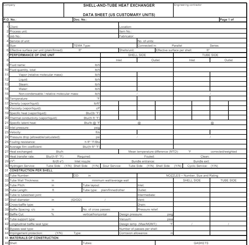
d. Equipment Datasheets
Equipment datasheets are documents that provide detailed specifications and design data for individual process equipment, such as vessels, heat exchangers, pumps, and compressors.
These datasheets include information on equipment dimensions, materials, operating conditions, and other technical data, serving as a basis for equipment procurement, fabrication, and inspection.
These datasheets shall be passed to manufacturers and other engineering disciplines for detailed design. That’s why all data shall be added with great care. API standards provide examples of how a datasheet looks like and typical information for different pieces of equipment.
e. Utility and Effluent Summary
A Utility and Effluent Summary is a document that provides an overview of the utility requirements and effluent streams for a chemical plant or process facility.
The utility summary includes information on the consumption of water, steam, electricity, and other utilities, as well as the production of by-products and waste streams.
The effluent summary outlines the composition, flow rates, and treatment requirements for process effluents, such as wastewater for example.
In addition, a relief load report is commonly issued by a process engineer. In the relief load summary, all loads from pressure safety valves and blowdown valves are stated as this shall be the basis for sizing the whole flare system.

These summaries are essential for the design and operation of utility systems and environmental control facilities, ensuring that the process meets its resource and compliance objectives.
f. Equipment List and Line List
An Equipment List provides detailed information on all process equipment, including equipment tag numbers, descriptions, specifications, and other relevant data.
A Line List focuses on the process piping system, providing information on pipe tag numbers, sizes, materials, and other details.
These lists serve as valuable resources for budget quotations and a rough estimation of project costs. They also serve for downstream engineering activities such as plant layout drawings and material takeoffs.
Process Engineering Masterclass
Become a Professional Process Engineer, discover process engineering career, role, activities and common practices with access to most of the courses here.
g. Control Philosophy
A Control Philosophy document defines the overall strategy for process control of different equipment in the plant. It outlines the specific control objectives for each process unit and selection of control variables, the design of control loops, and the integration of advanced control techniques. In the article 5 Tips to choose the best process control scheme, we have gone through the different practices used to choose the proper control of plant components.
The Control Philosophy serves as a guide for the design and implementation of the plant’s control system, ensuring that process performance and safety are maintained under a wide range of operating conditions. It is then passed to the control system vendor to apply the proper control logic of the plant.
h. Cause and Effect
Cause and Effect document, also known as a Cause and Effect Matrix or Shutdown Logic, is a systematic representation of the process safety interlocks and shutdown systems in a chemical plant or process facility. It outlines the various safety functions that are triggered by specific process events or conditions, such as high pressure, low temperature, or equipment failure.
For example, a cause and effect matrix is expected to show the logic tripping the pump in case of very low liquid level in the vessel from where it draws the liquid, or high pressure interlock to protect the piping by isolating the source of pressure,…etc. This is done using ESD or SIS systems that receive a signal from the instrument and send its output to the shutdown valve or pump motor.
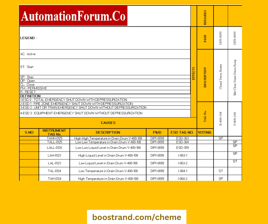
All the shutdown logic should be reflected in a document that shall be delivered to ESD system manufacturers to apply the shutdown protection logic in the plant.
i. Process Datasheets for Instruments
Process datasheets for instruments are documents that provide detailed specifications and design data for process instrumentation, such as pressure transmitters, flow meters, and temperature sensors.
These datasheets include the process requirements from the instruments, such as the expected flow or pressure or temperature operating range, the fluid physical properties, and the design pressure and temperatures.
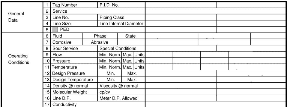
Based on these data, instrumentation engineers shall select the appropriate instruments and consider the proper instrument range and design. That’s why the data should be taken with care in order to procure the proper instrument that serves the function we need.
Conclusion
So we have seen how the role of a process engineer is highly important during a project execution. Based on the process design, all downstream activities carried out by different engineering disciplines.
In conclusion, mastering process design requires a deep understanding of core process design principles, key activities, and essential documents, as well as the effective use of simulation software and a thorough knowledge of the oil and gas and petrochemical industries.
By developing these skills and knowledge, process engineers can contribute to the development of efficient, safe, and sustainable processes that meet the world’s growing demand for energy and petrochemical products.
To master project execution in chemical engineering, it is essential to continuously learn, evaluate, and optimize processes, as well as to develop effective communication, collaboration, and leadership skills. By doing so, chemical engineers can contribute to the success of their projects and the overall growth and development of the chemical engineering profession.
Start your Career
Access Process Engineering Introduction Course
Share this:
[…] creation of a PFD is typically based on the output of process simulation software. We have discussed plant simulation’s role in a project in the previous article. In a nutshell, process simulation involves using specialized software to model and analyze the […]