Step 1
Reflux pump stops. No more reflux to the tower
Ensuring the proper protection of a chemical or oil and gas plant from overpressure is one of the major jobs of a process engineer. This is done by analyzing overpressure scenarios and applying different layers of protection. A pressure safety valve (PSV) is on these protection layers. Designed to release excess pressure within a system, PSVs are usually the last protection layer against potential hazards. Their failure to protect the system can lead to accidents and equipment failure.
That’s why a PSV should be well sized to handle the relief load that can happen due to potential overpressure. However, it’s not just about sizing. If a PSV not installed in the right position, it may not be able to function well. It may even be no more functioning, which can lead to overpressure in the system. As the PSV position is primarily shown on the Piping and Instrumentation Diagram (P&ID), a process engineer should be careful when preparing the P&ID in order to choose the optimum position.
In this article, we shall go through the major guidelines that should be considered when choosing the position of a PSV. So let’s start.
If you’d like to continue watching the video, you can check out the below. Otherwise, you can continue reading!
The most critical aspect of PSV positioning is their orientation. They should ideally be installed in a vertical position, with the stem facing upwards. In addition, the inlet line to the PSV is sloped towards the vessel.
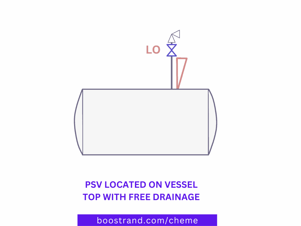
This positioning allows for free drainage of any liquid that may accumulate in the valve. If a liquid were to accumulate and block the valve, it could lead to PSV malfunction or even failure.
Positioning the PSV at the top of the vessel with free drainage ensures that there is no obstruction to the flow of liquid, preventing any possibility of blockage or undesirable flow regime. This is a common practice that is dictated by API 520 and should be clearly shown on the P&ID.
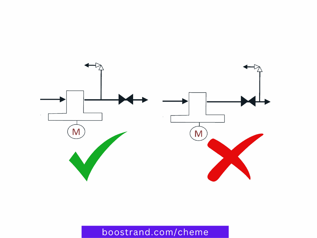
To ensure that the PSV shall do its job, the installation should be designed in such a way that there are no physical barriers or restrictions that could obstruct the flow during relieving. We can see this through different examples.
For example, when placing the PSV upstream of other valves, this means that the PSV shall open if the downstream valve is closed. However, if any valves of the installed valves upstream the PSV was closed, the PSV shall be isolated from the system it should be protecting.
This means that when protecting the system from valve blockage, the PSV should be installed before any of these valves to protect the system from overpressure. Otherwise, they would be useless and the system would be left unprotected.
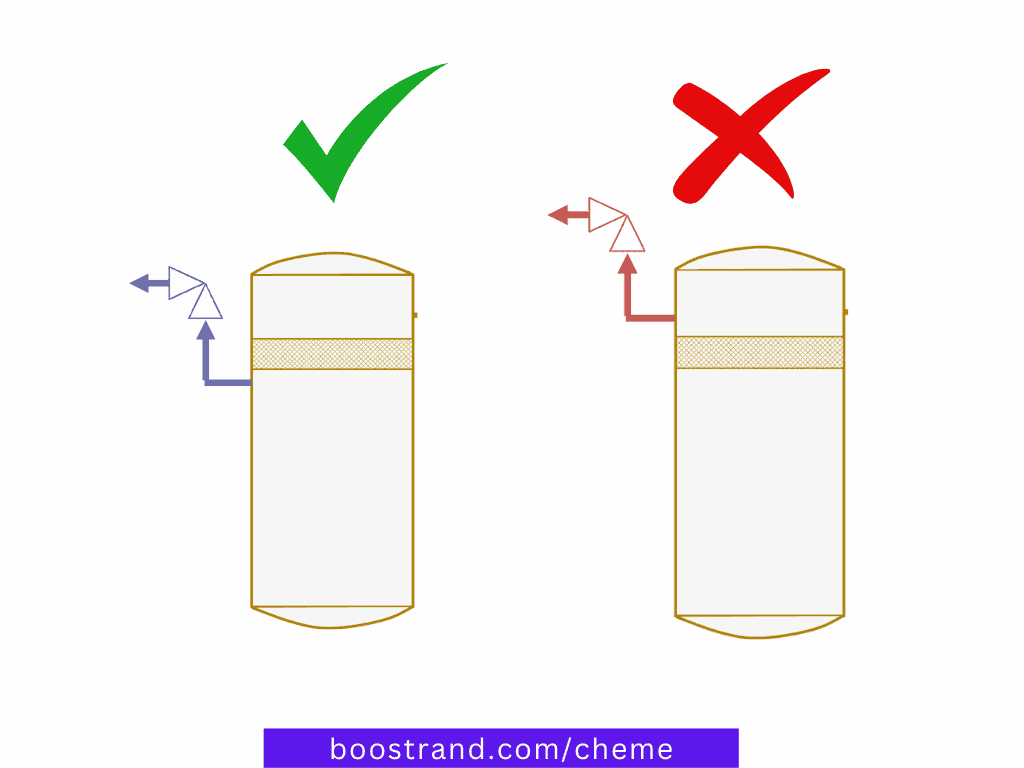
If a PSV is installed on a vessel with internals, for example a demister or a mist eliminator, it should be installed upstream of the internal. This is because a demister is subject to getting plugged or experiencing excessive pressure drop. So the PSV here should be installed upstream the demister to ensure vessel protection.
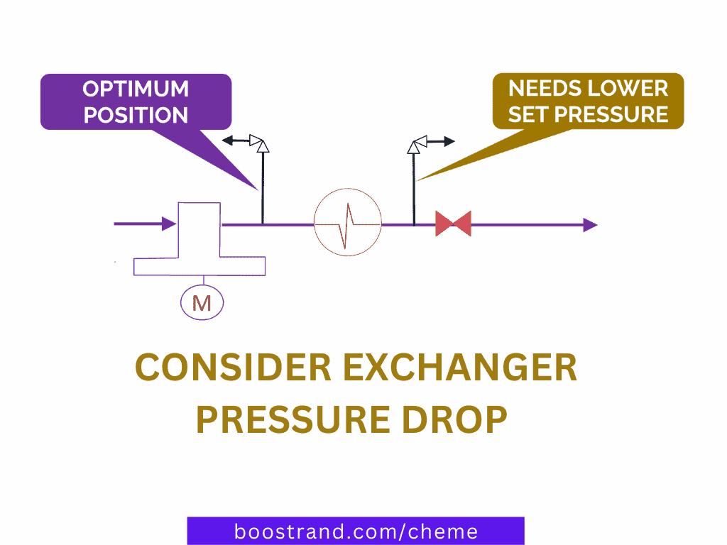
If a PSV is supposed to protect an exchanger, it should be placed upstream of the exchanger. This way, it shall not be affected by the pressure drop in the exchanger. If it was deemed necessary to place the PSV downstream the exchanger, the exchanger’s pressure drop should be subtracted from set pressure of the PSV. This is highly important because lowering the PSV set pressure shall lead to a larger PSV size.
So here again, a process engineer should take the position of a PSV with high care. When preparing the P&ID, he should identify all sources of blockage and ensure that they won’t hinder the PSV from opening when needed. This is even studied during HAZOP and SIL assessments to ensure that the current P&ID design is already considering the proper functioning of the PSV. In our P&ID course, we have gone through different common practices for a PSV, when we should add it, and how HAZOP and SIL studies ensure that the system has enough protection.
Learn PSV sizing for different scenarios, understand depressurization, blowdown & flare system components, and analysis.
When placing the PSV on the P&ID, a process engineer should expect what shall happen when the PSV opens and the path of the relieved fluid. This is highly important because this path can cause other safety issues.
Suppose we are having a fractionator overhead system, we need to protect both the tower and the reflux accumulator. That’s why we shall add a PSV to open in case the pressure reached the design pressure of the system.
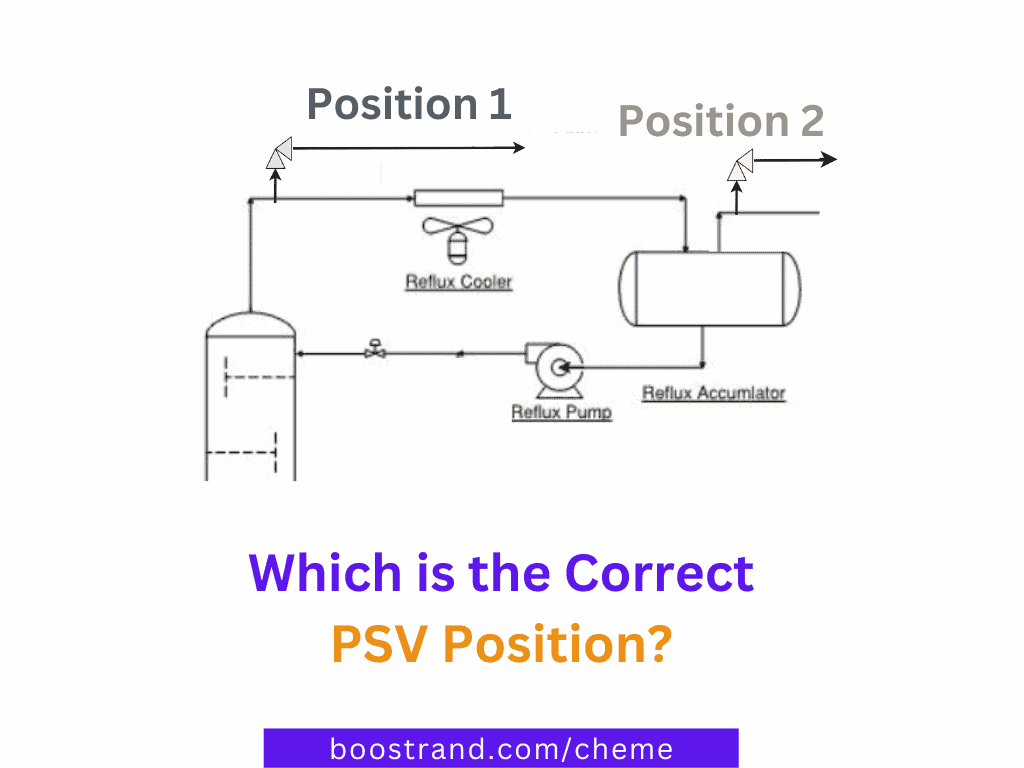
The question here would be; where shall we install the PSV?
Well, let’s start by answering the last question. When should we install one PSV for the whole system and when should we install 2 PSVs; one for the tower and the other for the vessel?
The answer to this question would lead us to another question: Are there any valves or restrictions on the path from the column to the accumulator? Or it’s an open flow path? Let’s analyse each case.
If we are dealing with an open flow path, which means that the line from the tower to the vessel passing through the condenser doesn’t have any valves. So here there shall be no means for blockage of this line.
In this case, we shall consider only ONE PSV for both the tower and the vessel. This leads us to the next question:
Where shall the PSV be placed?
Well, if we placed the PSV on the accumulator (Position 2 as shown in the photo), there may cause a severe issue. In order to understand this issue, we need to analyse how reflux failure scenario shall happen. Let’s see its steps:
Reflux pump stops. No more reflux to the tower
More vapors from column overhead due to loss of reflux.
Depending on the condenser’s design, more liquid shall be condensed in the overhead condenser.
Condensed liquids shall keep on going to the accumulator, while no liquid is getting out of the vessel because reflux pump isn’t working.
Level shall keep on accumulation in the vessel with no means to stop it or get it out of the vessel. Finally, accumulator shall overflow.
So here we see that it is totally an undesirable scenario that would lead to liquid overfilling in the accumulator. In addition, if we are talking about liquids at a high pressure and low temperature, as the case in deethanizers for example, the liquid shall even be subject to very low temperatures, which may cause metal embrittlement.
So here the correct position of the PSV shall be POSITION 1. In case, of reflux failure, the vapor shall be relieved before being introduced to the condenser, which shall avoid the vessel’s accumulation scenario. In case of other relief scenario in the accumulator, the relief load shall still have its path to the PSV at position 1. However, care should be taken to minimize the pressure drop from the accumulator up to the PSV as discussed in the article 4 Key Factors Affecting PSV Sizing & Operation.
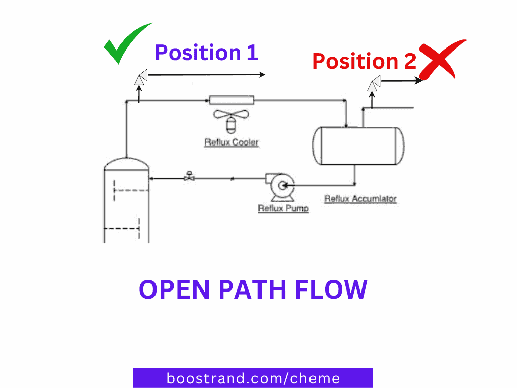
But what if the path from the tower to the accumulator has obstacles that shall cause blockage and isolate the tower from the vessel?
In this case we shall need a PSV on each system (BOTH POSITION 2 AND POSITION 1). If we applied what we discussed above, this block valve can isolate the PSV from the accumulator. This would leave the accumulator unprotected against overpressure scenarios.
This can be the case if there are any valves on the path from the tower to the accumulator that can be closed. Or if we are dealing with a dirty service on the condenser that can cause excessive fouling, leading to hindering the flow from the tower to the accumulator.
But what shall happen if the reflux pump failed? Won’t the reflux failure scenario above be credible as well?
Well, yes. As we are talking here about a reflux pump failure case, this block valve is expected to be open. This would mean that both systems shall be open to each other in the normal operation. So here, we want to ensure that the vapor relieved from the tower shall be relieved from Position 1 not Position 2 to avoid condensation of overhead gases and liquid overfilling in the accumulator.
That’s why we shall need to consider the set pressure at Position 1 to be SLIGHTLY LESS than that of Position 2 so that it shall open first and relieve the excess hot vapors.
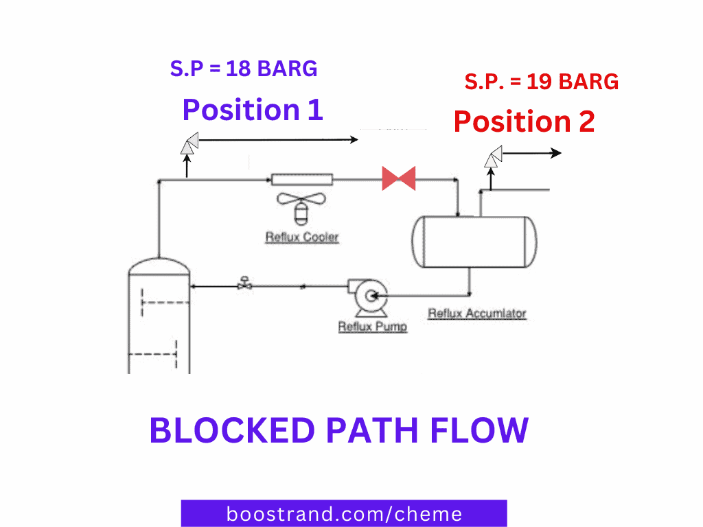
So to wrap things up, let’s consider the example in the photo above:
This way, we guarantee that both the tower, condenser and accumulator are all protected with both pressure safety valves.
The correct positioning of PSVs is a very critical to ensure overpressure protection in any chemical or oil and gas plant. A process engineer should follow the common practices and analyse overpressure scenarios in order to ensure that the PSV is in the proper position. By applying these practices, we can say that the PSV shall do its function and protect, system, equipment and personnel.
Access Process Engineering Introduction Course
[…] creation of a PFD is typically based on the output of process simulation software. We have discussed plant simulation’s role in a project in the previous article. In a nutshell, process simulation involves using specialized software to model and analyze the […]